1KR-FE ENGINE MECHANICAL CYLINDER HEAD GASKET REMOVAL
CAUTION / NOTICE / HINT
- NOTICE:
-
After the ignition switch is turned off, the radio and display receiver assembly records various types of memory and settings. As a result, after turning the ignition switch off, make sure to wait at least 120 seconds before disconnecting the cable from the negative (-) auxiliary battery terminal.
- HINT:
-
When the cable is disconnected/reconnected to the auxiliary battery terminal, systems temporarily stop operating. However, each system has a function that completes learning the first time the system is used.
- ·
Learning completes when vehicle is driven
Effect/Inoperative Function When Necessary Procedures are not Performed Necessary Procedures Link Lane tracing assist system Drive the vehicle straight ahead at 35 km/h (22 mph) or more for 5 second or more. (  )
Pre-collision system Stop and start system Drive the vehicle until stop and start control is permitted (approximately 5 to 60 minutes) ( )
·Learning completes when vehicle is operated normally
Effect/Inoperative Function When Necessary Procedures are not Performed Necessary Procedures Link Power door lock control system
·Back door opener
Perform door unlock operation with door control switch or electrical key transmitter sub-assembly switch. ( )
Air conditioning system After the ignition switch is turned to ON, the servo motor standard position is recognized. -
PROCEDURE

 1.INSTALL ENGINE TO ENGINE STAND
2.REMOVE ENGINE HANGER
17111
3.REMOVE INTAKE MANIFOLD
16261G
4.REMOVE WATER BY-PASS HOSE ASSEMBLY
29603B
5.REMOVE OIL LEVEL GAUGE GUIDE OIL HOSE
15301
6.REMOVE ENGINE OIL LEVEL DIPSTICK
11409
7.REMOVE ENGINE OIL LEVEL DIPSTICK GUIDE
89481B
8.REMOVE DIFFERENTIAL PRESSURE SENSOR (w/ Differential Pressure Sensor)
17118
9.REMOVE MANIFOLD STAY
17140A
10.REMOVE EXHAUST MANIFOLD ASSEMBLY
11101E
11.REMOVE CAMSHAFT POSITION SENSOR (for Exhaust Side)
11101J
12.REMOVE CAMSHAFT TIMING OIL CONTROL VALVE ASSEMBLY (for Intake Side)
11101J
13.REMOVE CAMSHAFT TIMING OIL CONTROL VALVE ASSEMBLY (for Exhaust Side)
11301K
14.REMOVE CRANKSHAFT POSITION SENSOR
19500D
15.REMOVE NO. 1 IGNITION COIL
11201
16.REMOVE CYLINDER HEAD COVER SUB-ASSEMBLY
11213
17.REMOVE CYLINDER HEAD COVER GASKET
16268L
18.REMOVE WATER BY-PASS PIPE
19.SET NO. 1 CYLINDER TO TDC/EXHAUST
12101
20.REMOVE OIL PAN SUB-ASSEMBLY
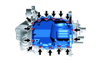
Remove the 13 bolts and 2 nuts.
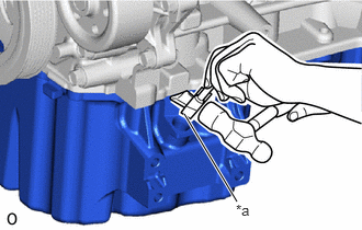
| *a | Oil Pan Seal Cutter |
Insert the blade of an oil pan seal cutter between the oil pan sub-assembly and cylinder block sub-assembly. Cut through the applied sealer and remove the oil pan sub-assembly.
- NOTICE:
-
Be careful not to damage the contact surfaces of the oil pan sub-assembly.
16100
21.REMOVE ENGINE WATER PUMP ASSEMBLY
15671
22.REMOVE OIL FILTER BRACKET
13471
23.REMOVE CRANKSHAFT PULLEY
11310
24.REMOVE TIMING CHAIN COVER SUB-ASSEMBLY
11302A
25.REMOVE TIMING CHAIN COVER OIL SEAL
13540
26.REMOVE NO. 1 CHAIN TENSIONER ASSEMBLY
13591
27.REMOVE TIMING CHAIN TENSION ARM
13506
28.REMOVE CHAIN SUB-ASSEMBLY
13521
29.REMOVE CRANKSHAFT TIMING SPROCKET
13566B
30.REMOVE TIMING CHAIN GUIDE
31.REMOVE BRACKET
13520
32.REMOVE CAMSHAFT TIMING SPROCKET ASSEMBLY
33.REMOVE CAMSHAFT BEARING CAP
15678A
34.REMOVE OIL CONTROL VALVE FILTER
13512
35.REMOVE NO. 2 CAMSHAFT
13511
36.REMOVE CAMSHAFT
11101
37.REMOVE CYLINDER HEAD SUB-ASSEMBLY
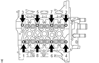
Using an 8 mm bi-hexagon wrench, uniformly loosen and remove the 8 cylinder head set bolts and 8 plate washers in several steps in the order shown in the illustration.
- NOTICE:
- ·
Cylinder head sub-assembly warpage or cracking may result from removing the bolts in the wrong order.
·Do not drop the washers into the cylinder head sub-assembly.
Remove the cylinder head sub-assembly from the cylinder block sub-assembly.
11115
38.REMOVE CYLINDER HEAD GASKET
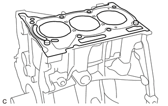
Remove the cylinder head gasket from the cylinder block sub-assembly.