B48 ENGINE MECHANICAL PISTON INSTALLATION
PROCEDURE

 1.INSTALL PISTON RING
- CAUTION:
- ·
Very wide spreading of the piston rings during installation / removal.
·Damage to the piston rings.
-Spread the piston rings only until the piston ring can just be slid over the piston.
-Use piston ring pliers to install and remove the piston rings.
·Clean the used pistons carefully. Do not use a metal-cutting tool to avoid damaging the pistons.
·Wear safety goggles.
- NOTICE:
-
The description is for one component only. The procedure is identical for all further components.
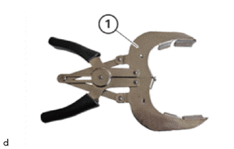
Keep the standard piston ring pliers (1) ready.
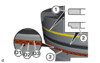
Correctly prepare the piston rings:
Upper piston ring (1): Plain rectangular compression ring (engraving must point upwards)
Centre piston ring (2): Taper faced piston ring (engraving must point upwards)
Oil scraper ring (3): consists of 2 piston rings ((O1), (O3)) with a spring (O2) in the centre.
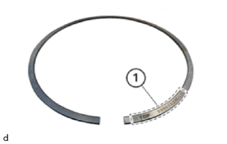
Make sure that the assembly mark TOP (1) points to the top to the combustion chamber.
If there is no assembly mark TOP (1), then the piston ring with the writing must point to the top to the combustion chamber.
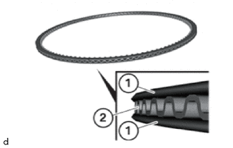
Attach the oil scraper rings (1) and springs (2) manually (see following steps).
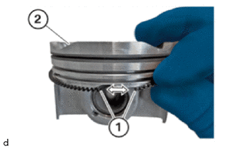
Slide the spring (1) on to the piston (2) and install it.
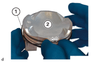
Slide the two oil scraper rings (1) on to the piston (2) and install them.
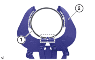
Position the centre piston ring (1) in the marked area at the piston ring pliers (2).
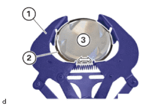
Clamp the piston ring pliers (1) in the direction of arrow and feed in the centre piston ring (2) in the piston (3) and install it.
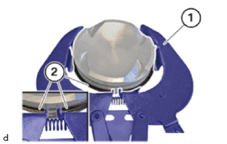
Release the piston ring pliers (1) at the centre piston ring (2).
Feed out the piston ring pliers (1) at the centre piston ring (2) and remove it.
Position the upper piston ring (1) in the marked area at the piston ring pliers (2).
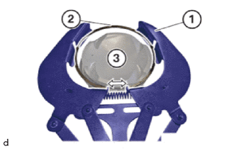
Clamp the piston ring pliers (1) in the direction of arrow and feed in the upper piston ring (2) in the piston (3) and install it.
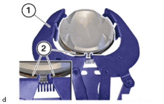
Release the piston ring pliers (1) at the upper piston ring (2).
Feed out the piston ring pliers (1) at the upper piston ring (2) and remove it.
2.INSTALL PISTON
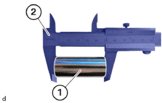
Determine the length of the piston pin (1) with a verier caliper (2).
- Piston pin length:
55 mm (2.17 in.)
- HINT:
-
Before replacing the piston, the length of the piston pin must be measured.
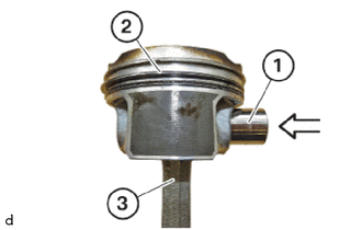
Install piston pin (1) in piston (2) and connecting rod (3).
- HINT:
- ·
Piston and piston pin are matched to each other.
Always install piston and piston pin together and do not switch by mistake.
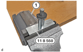
Secure the special tool 0 495 743 (11 8 560) on the vice.
- SST
- 09200-WA740
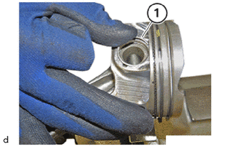
Position the piston pin hole snap ring (1) with the opening of the piston pin hole snap ring (1) facing the piston top side.
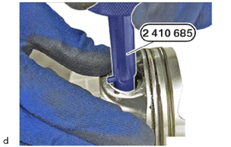
Preload the piston pin hole snap ring with your thumb.
At the same time, press the piston pin hole snap ring into the piston using the special tool 2 410 685.
- SST
- 09200-WA580
Do not push and turn the special tool 2 410 685 at the same time. Otherwise, the piston pin hole snap ring will be unscrewed from the piston again.
- SST
- 09200-WA580
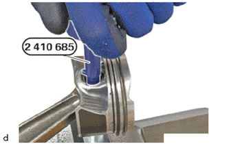
Secure the piston pin hole snap ring with your thumb.
Reset the special tool 2 410 685 and continue to press the piston pin hole snap ring into the piston.
- SST
- 09200-WA580
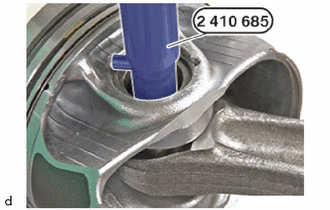
Secure the piston pin hole snap ring with your thumb.
Reset the special tool 2 410 685 and press the piston pin hole snap ring fully into the piston.
- SST
- 09200-WA580
3.INSPECT CYLINDER BORE
- HINT:
-
The description is for one component only. The procedure is identical for all further components.
Prerequisite
Cylinder barrel is cleaned.
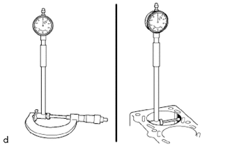
Adjusting measuring screw to nominal dimension of cylinder bore.
- Cylinder bore:
Distance from the upper edge of the cylinder barrel to the measuring point Diameter of cylinder bore Permitted irregularity of the cylinder bore 0 to 60 mm (0 to 2.36 in.) 82.000 to 82.014 mm (3.228 to 3.229 in.) 0.007 mm (0.000276 in.) 60 to 80 mm (2.36 to 3.15 in.) 82.008 to 82.022 mm (3.2287 to 3.2292 in.) 0.007 mm (0.000276 in.) 80 to 115 mm (3.15 to 4.53 in.) 82.021 to 82.037 mm (3.2292 to 3.2298 in.) 0.007 mm (0.000276 in.) 115 to 135 mm (4.53 to 5.31 in.) 82.033 to 82.057 mm (3.230 to 3.231 in.) 0.010 mm (0.000394 in.)
Insert internal measuring device into the micrometer and set to zero.
With the internal measuring device, measure the cylinder at the following points and check the deviations from the nominal dimension.
Lower third of the cylinder bore in direction of travel,
Lower third of the cylinder bore transversely to direction of travel,
Middle third of the cylinder bore in direction of travel,
Middle third of the cylinder bore transversely to direction of travel,
Upper third of the cylinder bore in direction of travel,
Upper third of the cylinder bore transversely to direction of travel.
- Cylinder bore:
Distance from the upper edge of the cylinder barrel to the measuring point Diameter of cylinder bore Permitted irregularity of the cylinder bore 0 to 60 mm (0 to 2.36 in.) 82.000 to 82.014 mm (3.228 to 3.229 in.) 0.007 mm (0.000276 in.) 60 to 80 mm (2.36 to 3.15 in.) 82.008 to 82.022 mm (3.2287 to 3.2292 in.) 0.007 mm (0.000276 in.) 80 to 115 mm (3.15 to 4.53 in.) 82.021 to 82.037 mm (3.2292 to 3.2298 in.) 0.007 mm (0.000276 in.) 115 to 135 mm (4.53 to 5.31 in.) 82.033 to 82.057 mm (3.230 to 3.231 in.) 0.010 mm (0.000394 in.)
- HINT:
-
If the cylinder bore is not as specified, replace the crankcase.
13201
4.INSTALL CONNECTING ROD SUB-ASSEMBLY
- NOTICE:
- ·
Damage on the cylinder wall and oil spray nozzles.
Major force can scratch the cylinder wall and bend the oil spray nozzles.
-Carefully move the piston and connecting rod in the engine block.
- HINT:
-
The description is for one component only. The procedure is identical for all further components.
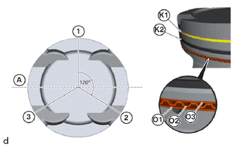
Align the contact points of all piston rings by 120° each.
Do not position contact points over axis of gudgeon pin (A).
| Position number | Description |
|---|---|
| 1 | 12 o'clock position |
| 2 | 4 o'clock position |
| 3 | 8 o'clock position |
| A | Axis of gudgeon pin |
| K1 | 1. Piston ring (plain rectangular compression ring) |
| K2 | 2. Piston ring (taper faced piston ring) |
| O1 | Oil scraper ring below |
| O2 | Spiral expander |
| O3 | Oil scraper ring above |
| Piston ring | Align at the following position |
|---|---|
| Upper oil scraper ring (O3) | Align at the 12 o'clock position (1) |
| Spiral expander (O2) | Align at the 4 o'clock position (2) |
| Lower oil scraper ring (O1) | Align at the 8 o'clock position (3) |
| Taper faced piston ring (K2) | Align at the 12 o'clock position (1) |
| Plain rectangular compression ring (K1) | Align at the 4 o'clock position (2) |
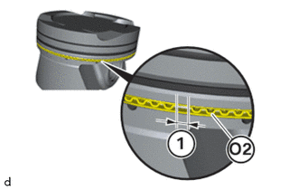
Make sure that contact point (1) does not overlap spring (O2).
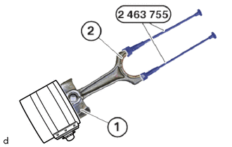
Coat the pistons (1) and piston rings lightly with oil.
Insert the piston (1) with the piston rings into the piston ring compressor.
Screw special tool 2 463 755 on at large connecting rod eye (2).
- SST
- 09200-WA730
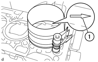
Align the piston so that the arrow (1) points to cylinder 1.
Insert piston with the connecting rod into the piston ring compressor and guide it into the cylinder.
- NOTICE:
- ·
Damage on the cylinder wall and oil spray nozzles.
Major force can scratch the cylinder wall and bend the oil spray nozzles.
-Carefully move the piston and connecting rod in the engine block.
5.INSTALL CONNECTING ROD CAP
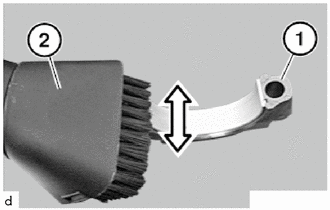
Vacuum the connecting rod bearing and cracked surface (1) with a vacuum cleaner (2).
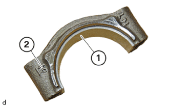
Insert the connecting rod bearing (1) into the connecting rod bearing cap (2).
Apply a light coat of oil to the connecting rod bearing (1).
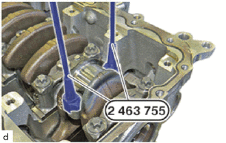
If necessary, screw the special tool (assembly tool) 2 463 755 into the large connecting rod eye.
- SST
- 09200-WA730
Pull the connecting rod up to the connecting rod bearing journal.
- NOTICE:
- ·
Engine damage caused by incorrectly installed connecting rod bearings and connecting rod bearing caps.
Engine damage may result from incorrectly installing connecting rod bearings and connecting rod bearing caps.
-Always install all connecting rod bearings and connecting rod bearing caps in the same position from which they were removed.
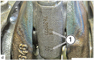
Attach the connecting rod bearing caps to the connecting rod until the designations (1) match.
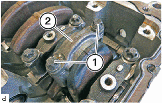
Replace bolts (1).
Step 1:
Tighten the E12 bolts.
- Torque:
- 20 N*m (204 kgf*cm, 15 ft.*lbf)
Step 2:
- SST
- 09900-WA010
Using SST, tighten the E12 bolts (1) an additional 70°.
- HINT:
-
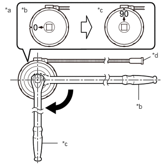 2.99,1.271 3.156,1.188 false 2.906,2.094 2.906,1.76 false 0.875,3 1.208,3 false 0.104,0.125 0.417,0.281 0.313,0.156 10 false *a 0.448,0.125 0.76,0.281 0.313,0.156 10 false *b 2.042,0.125 2.354,0.281 0.313,0.156 10 false *c 3.188,1.073 3.427,1.271 0.24,0.198 10 false *d 2.854,2.146 3.167,2.302 0.313,0.156 10 false *b 1.302,2.927 1.615,3.083 0.313,0.156 10 false *c
*a Example *b Before Tightening *c After Tightening *d Magnetic Portion
- ·
The magnetic portion is used to secure the gauge to the vehicle.
·After first adjusting the needle of the gauge to 0°, tighten to the specified angle.
·Perform the work procedure carefully so that the gauge, etc. does not become tilted.
Step 3:
Using SST, tighten the E12 bolts (1) an another 70°.
- SST
- 09900-WA010
- HINT:
-
2.99,1.271 3.156,1.188 false 2.906,2.094 2.906,1.76 false 0.875,3 1.208,3 false 0.104,0.125 0.417,0.281 0.313,0.156 10 false *a 0.448,0.125 0.76,0.281 0.313,0.156 10 false *b 2.042,0.125 2.354,0.281 0.313,0.156 10 false *c 3.188,1.073 3.427,1.271 0.24,0.198 10 false *d 2.854,2.146 3.167,2.302 0.313,0.156 10 false *b 1.302,2.927 1.615,3.083 0.313,0.156 10 false *c
*a Example *b Before Tightening *c After Tightening *d Magnetic Portion
- ·
The magnetic portion is used to secure the gauge to the vehicle.
·After first adjusting the needle of the gauge to 0°, tighten to the specified angle.
·Perform the work procedure carefully so that the gauge, etc. does not become tilted.
12121
6.INSTALL NO. 1 OIL PAN BAFFLE PLATE
15100
7.INSTALL OIL PUMP ASSEMBLY
12101
8.INSTALL OIL PAN SUB-ASSEMBLY
9. SEALING OIL DUCT
10.CLEAN SEALING SURFACES
11115
11.INSTALL CYLINDER HEAD GASKET
12.SET NO. 1 CYLINDER TO TDC (COMPRESSION)
11101
13.INSTALL CYLINDER HEAD SUB-ASSEMBLY
14.ADJUST CAMSHAFT
13070A
15.INSTALL CAMSHAFT TIMING EXHAUST GEAR ASSEMBLY
135A0A
16.TEMPORARILY TIGHTEN EXHAUST CAMSHAFT TIMING GEAR BOLT ASSEMBLY
13050
17.INSTALL CAMSHAFT TIMING GEAR ASSEMBLY
135A0
18.TEMPORARILY TIGHTEN INTAKE CAMSHAFT TIMING GEAR BOLT ASSEMBLY
13506
19.TEMPORARILY INSTALL CHAIN SUB-ASSEMBLY
135A0
20.FULLY TIGHTEN INTAKE CAMSHAFT TIMING GEAR BOLT ASSEMBLY
135A0A
21.FULLY TIGHTEN EXHAUST CAMSHAFT TIMING GEAR BOLT ASSEMBLY
22.REMOVE SST
13540
23.INSTALL NO. 1 CHAIN TENSIONER ASSEMBLY
24.INSPECT CAMSHAFT TIMING
25.INSTALL SPARK PLUG
15474
26.INSTALL OUTLET TURBO OIL PIPE
17111
27.INSTALL INTAKE MANIFOLD
23285A
28.INSTALL NO. 1 CHECK VALVE
11201
29.INSTALL CYLINDER HEAD COVER SUB-ASSEMBLY
15370J
30.INSTALL CAM TIMING OIL CONTROL SOLENOID ASSEMBLY
23250B
31.REPLACE FUEL INJECTOR SEAL
23250
32.INSTALL FUEL INJECTOR ASSEMBLY
23470
33.ADJUST FUEL PUMP LIFTER ASSEMBLY
23100X
34.INSTALL FUEL (ENGINE ROOM SIDE) PUMP ASSEMBLY
23801P
35.INSTALL NO. 1 FUEL PIPE SUB-ASSEMBLY
36.ADD ENGINE OIL
37.INSTALL ENGINE ASSEMBLY