U241E AUTOMATIC TRANSMISSION / TRANSAXLE TRANSMISSION CONTROL CABLE REPLACEMENT
PROCEDURE

 1.DISCONNECT CABLE FROM NEGATIVE BATTERY TERMINAL
- CAUTION:
-
Wait at least 90 seconds after disconnecting the cable from the negative (-) battery terminal to prevent airbag and seat belt pretensioner activation.
17705
2.REMOVE AIR CLEANER CAP
Remove the air cleaner cap (see page Engine / Hybrid System>2AZ-FE ENGINE CONTROL>THROTTLE BODY>REMOVAL).
17700
3.REMOVE AIR CLEANER CASE
28800
4.REMOVE BATTERY
33554H
5.REMOVE SHIFT LOCK RELEASE BUTTON COVER (for RHD)
33504F
6.REMOVE SHIFT LEVER KNOB SUB-ASSEMBLY (for RHD)
7.REMOVE CENTER INSTRUMENT CLUSTER FINISH PANEL ASSEMBLY (for RHD)
55041B
8.REMOVE NO. 1 INSTRUMENT PANEL BOX DOOR SUB-ASSEMBLY (for RHD)
55042B
9.REMOVE NO. 2 INSTRUMENT PANEL BOX DOOR SUB-ASSEMBLY (for RHD)
55550
10.REMOVE GLOVE COMPARTMENT DOOR ASSEMBLY (for RHD)
55607
11.REMOVE NO. 2 INSTRUMENT PANEL UNDER COVER SUB-ASSEMBLY (for RHD)
67913B
12.REMOVE FRONT DOOR SCUFF PLATE RH (for RHD)
62111C
13.REMOVE COWL SIDE TRIM BOARD RH (for RHD)
55606
14.REMOVE NO. 1 INSTRUMENT PANEL UNDER COVER SUB-ASSEMBLY (for RHD)
55432B
15.REMOVE INSTRUMENT PANEL FINISH PANEL LOWER (for RHD)
58534E
16.REMOVE FLOOR CARPET COVER CENTER LH (for LHD)
58534E
17.REMOVE FLOOR CARPET COVER CENTER LH (for RHD)
58533C
18.REMOVE FLOOR CARPET COVER CENTER RH (for RHD)
55434B
19.REMOVE INSTRUMENT PANEL FINISH PANEL LOWER CENTER (for RHD)
55475B
20.REMOVE CENTER INSTRUMENT CLUSTER FINISH PANEL GARNISH (for RHD)
33820B
21.REMOVE TRANSAXLE CONTROL CABLE ASSEMBLY
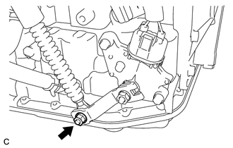
Remove the nut and disconnect the transmission control cable assembly from the control shaft lever.
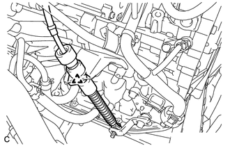
Remove the clip and separate the transmission control cable assembly from the No. 1 transmission control cable bracket.
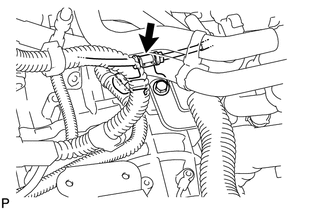
Disconnect the control cable from the control cable support.
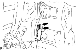
Remove the 2 nuts and disconnect the clamp of the control cable.
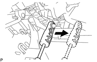
Disconnect the control cable from the shift lever.
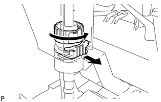
Using a screwdriver, pull out the stopper of the transmission control cable.
- NOTICE:
-
Do not remove the stopper. If the stopper is removed, reinstall it to its original position.
Rotate the nut counterclockwise approximately 180° and, while holding the nut in that position, disconnect the transmission control cable from the shift lever retainer.
- NOTICE:
-
Do not over rotate the nut as it will come off the interior spring and the transmission control cable will not be reusable.
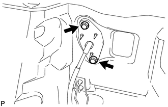
Remove the 2 bolts and control cable.
33820B
22.INSTALL TRANSAXLE CONTROL CABLE ASSEMBLY
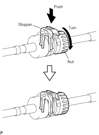
Rotate the transmission control cable nut counterclockwise approximately 180° and, while holding the nut in that position, press in the stopper until it makes 2 "click" sounds.
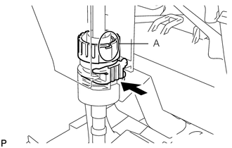
Install the cable outer of the transmission control cable to the shift lever retainer, check that the position of the spring is the same as A shown in the illustration, and press in the stopper.
- HINT:
-
If the stopper cannot be pressed in, slightly rotate the nut clockwise and then press in the stopper.
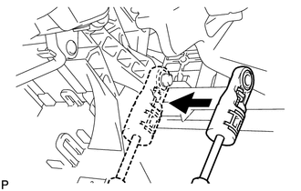
Connect the control cable to the shift lever.
- NOTICE:
-
Make sure the cable is installed to the base of the pin.
Install the control cable with the 2 bolts.
- Torque:
- 5.0 N*m (51 kgf*cm, 44 in.*lbf)
Fix the control cable onto the control cable bracket with the clip.
Connect the control cable onto the control shaft lever with the nut.
- Torque:
- 12 N*m (122 kgf*cm, 9 ft.*lbf)
Connect the clamp of the control cable with the 2 nuts.
- Torque:
- 12 N*m (122 kgf*cm, 9 ft.*lbf)
Connect the control cable to the cable support.
17700
23.INSTALL AIR CLEANER CASE
17705
24.INSTALL AIR CLEANER CAP
Install the air cleaner cap (see page Engine / Hybrid System>2AZ-FE ENGINE CONTROL>THROTTLE BODY>INSTALLATION).
25.INSTALL BATTERY
26.CONNECT CABLE TO NEGATIVE BATTERY TERMINAL
27.INSPECT SHIFT LEVER POSITION
When shifting the lever from P to the R position with the ignition switch on (IG) and the brake pedal depressed, make sure that the shift lever moves smoothly and moves correctly into position.
Start the engine and make sure that the vehicle moves forward when moving the lever from N to the D position and moves rearward when moving the lever to the R position.
If the operation cannot be performed as specified, inspect the park/neutral position switch and check the shift lever installation condition.
28.ADJUST SHIFT LEVER POSITION (for LHD)
29.ADJUST SHIFT LEVER POSITION (for RHD)
55475B
30.INSTALL CENTER INSTRUMENT CLUSTER FINISH PANEL GARNISH (for RHD)
55434B
31.INSTALL INSTRUMENT PANEL FINISH PANEL LOWER CENTER (for RHD)
58533C
32.INSTALL FLOOR CARPET COVER CENTER RH (for RHD)
58534E
33.INSTALL FLOOR CARPET COVER CENTER LH (for LHD)
58534E
34.INSTALL FLOOR CARPET COVER CENTER LH (for RHD)
55432B
35.INSTALL INSTRUMENT PANEL FINISH PANEL LOWER (for RHD)
55606
36.INSTALL NO. 1 INSTRUMENT PANEL UNDER COVER SUB-ASSEMBLY (for RHD)
62111C
37.INSTALL COWL SIDE TRIM BOARD RH (for RHD)
67913B
38.INSTALL FRONT DOOR SCUFF PLATE RH (for RHD)
55607
39.INSTALL NO. 2 INSTRUMENT PANEL UNDER COVER SUB-ASSEMBLY (for RHD)
55550
40.INSTALL GLOVE COMPARTMENT DOOR ASSEMBLY (for RHD)
55042B
41.INSTALL NO. 2 INSTRUMENT PANEL BOX DOOR SUB-ASSEMBLY (for RHD)
55041B
42.INSTALL NO. 1 INSTRUMENT PANEL BOX DOOR SUB-ASSEMBLY (for RHD)
43.INSTALL CENTER INSTRUMENT CLUSTER FINISH PANEL ASSEMBLY (for RHD)
33504F
44.INSTALL SHIFT LEVER KNOB SUB-ASSEMBLY (for RHD)
33554H
45.INSTALL SHIFT LOCK RELEASE BUTTON COVER (for RHD)
46.PERFORM INITIALIZATION
Perform initialization (see page General>INTRODUCTION>REPAIR INSTRUCTION>INITIALIZATION).
- NOTICE:
-
Certain systems need to be initialized after disconnecting and reconnecting the cable from the negative (-) battery terminal.