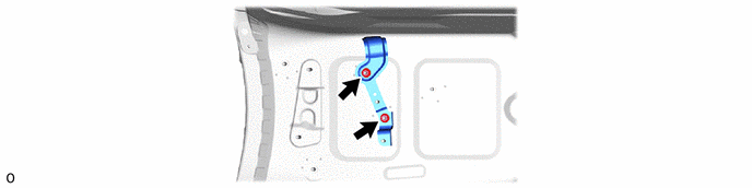
HYBRID / BATTERY CONTROL FRAME WIRE REMOVAL
CAUTION / NOTICE / HINT
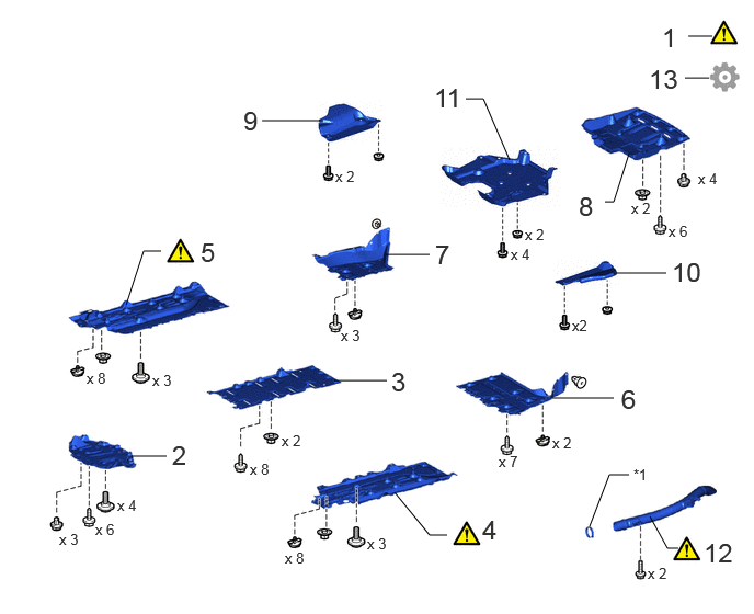
| Procedure | Part Name Code | 
|

|

|
|
|---|---|---|---|---|---|
| 1 | CAUTIONS FOR COMPRESSED HYDROGEN GAS | - | ( ) |
- | - |
| 2 | REAR NO. 4 FLOOR BOARD SUB-ASSEMBLY | 58404B | - | - | - |
| 3 | REAR NO. 3 FLOOR BOARD SUB-ASSEMBLY | 58403L | - | - | - |
| 4 | NO. 2 FLOOR BOARD SUB-ASSEMBLY | 58402K | ()
|
- | - |
| 5 | NO. 1 FLOOR BOARD SUB-ASSEMBLY | 58401M | ()
|
- | - |
| 6 | REAR FLOOR SIDE MEMBER COVER LH | 57628E | - | - | - |
| 7 | REAR FLOOR SIDE MEMBER COVER RH | 57627G | - | - | - |
| 8 | NO. 1 FLOOR UNDER COVER | 58398F | - | - | - |
| 9 | NO. 1 DIFFERENTIAL SUPPORT PROTECTOR | 52383E | - | - | - |
| 10 | NO. 2 DIFFERENTIAL SUPPORT PROTECTOR | 52384C | - | - | - |
| 11 | REAR SUSPENSION BRACE COVER | 53661B | - | - | - |
| 12 | NO. 3 FC EXHAUST PIPE | 17DB3 | ()
|
- | - |
| 13 | PRESSURE RELEASE OPERATION | - | - | - | ()
|
| Procedure | Part Name Code |
|
|
|
|
|---|---|---|---|---|---|
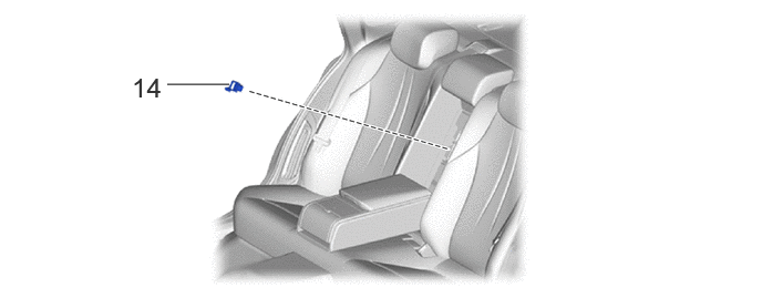
| 14 | SERVICE PLUG GRIP | G3834 | - | - | - |
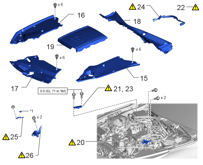
| Procedure | Part Name Code |
|
|
|
|
|---|---|---|---|---|---|
| 15 | UPPER RADIATOR SUPPORT SEAL | 53292A | - | - | - |
| 16 | RADIATOR COVER PLATE | 53291B | - | - | - |
| 17 | LOWER RADIATOR AIR DEFLECTOR | 53295 | - | - | - |
| 18 | COWL TOP VENTILATOR LOUVER SUB-ASSEMBLY | 55708 | - | - | - |
| 19 | FC STACK COVER SUB-ASSEMBLY | 1A906 | - | - | - |
| 20 | FC CONVERTER POWER OUTLET CABLE (INVERTER WITH CONVERTER ASSEMBLY) | G9200A | ()
|
- | - |
| 21 | REMOVE CONNECTOR COVER ASSEMBLY | - | ()
|
- | - |
| 22 | CHECK TERMINAL VOLTAGE | - | ()
|
- | - |
| 23 | INSTALL CONNECTOR COVER ASSEMBLY | - | ()
|
- | - |
| 24 | NO. 1 BATTERY PACK WIRE | 821H3A | ()
|
- | - |
| 25 | NO. 4 FC JUNCTION CABLE BRACKET | G9A84C | ()
|
- | - |
| 26 | FLOOR UNDER WIRE | 821H1 | ()
|
- | - |
| *1 | BATTERY COVER LOCK STRIKER | - | - |

|
N*m (kgf*cm, ft.*lbf): Specified torque | - | - |
| Procedure | Part Name Code |
|
|
|
|
|---|---|---|---|---|---|
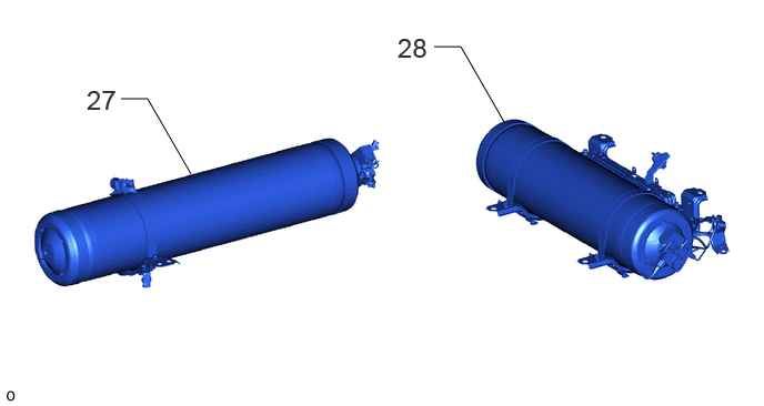
| 27 | NO. 1 HYDROGEN TANK ASSEMBLY | 77A10 | - | - | - |
| 28 | NO. 2 HYDROGEN TANK ASSEMBLY | 77A20 | - | - | - |
| Procedure | Part Name Code |
|
|
|
|
|---|---|---|---|---|---|
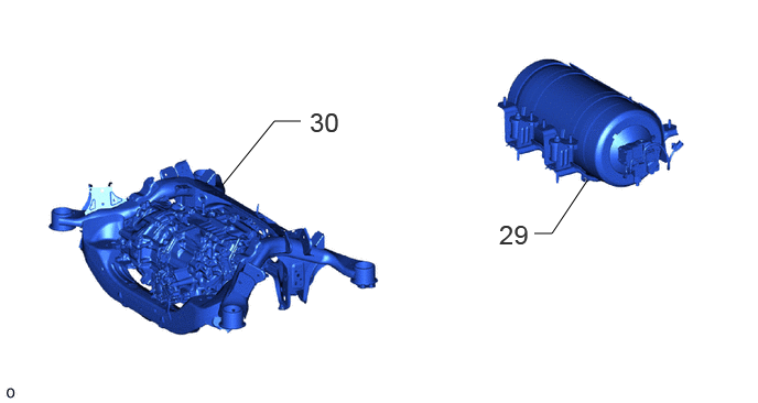
| 29 | NO. 3 HYDROGEN TANK ASSEMBLY | 77A30 | - | - | - |
| 30 | REAR SUSPENSION MEMBER SUB-ASSEMBLY | 51206A | - | - | - |
| Procedure | Part Name Code |
|
|
|
|
|---|---|---|---|---|---|
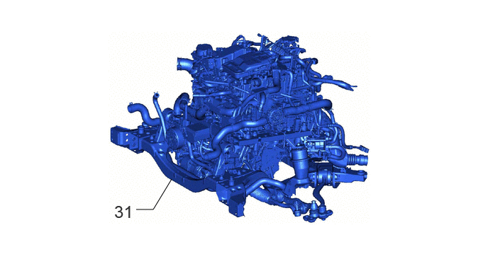
| 31 | FC CONVERTER WITH FC STACK ASSEMBLY | - | - | - | - |
| Procedure | Part Name Code |
|
|
|
|
|---|---|---|---|---|---|
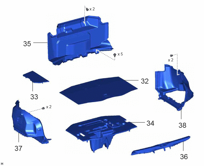
| 32 | LUGGAGE COMPARTMENT MAT SUB-ASSEMBLY | 64701 | - | - | - |
| 33 | LUGGAGE COMPARTMENT TRIM COVER LH | 64715D | - | - | - |
| 34 | TOOL BOX | 75201A | - | - | - |
| 35 | FRONT LUGGAGE COMPARTMENT TRIM COVER | 64075B | - | - | - |
| 36 | REAR FLOOR FINISH PLATE | 58387 | - | - | - |
| 37 | LUGGAGE COMPARTMENT TRIM COVER INNER LH | 64722 | - | - | - |
| 38 | LUGGAGE COMPARTMENT TRIM COVER INNER RH | 64721 | - | - | - |
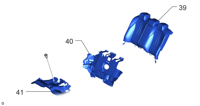
| Procedure | Part Name Code |
|
|
|
|
|---|---|---|---|---|---|
| 39 | BENCH TYPE REAR SEATBACK ASSEMBLY | - | - | - | - |
| 40 | NO. 1 ROOM PARTITION PAD | 64273D | - | - | - |
| 41 | NO. 6 FLOOR MAT | 58516A | - | - | - |
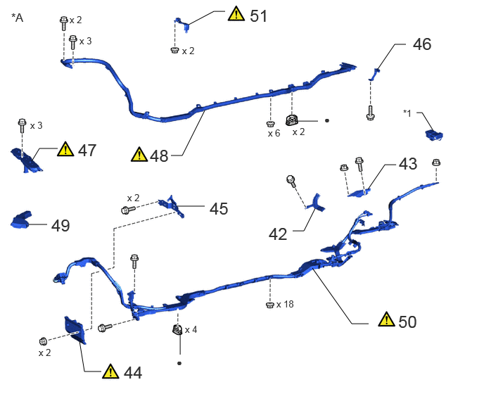
| Procedure | Part Name Code |
|
|
|
|
|---|---|---|---|---|---|
| 42 | WIRE HARNESS CLAMP BRACKET | - | - | - | - |
| 43 | WIRE HARNESS CLAMP BRACKET | - | - | - | - |
| 44 | NO. 9 WIRING HARNESS PROTECTOR | 82817J | ()
|
- | - |
| 45 | WIRE HARNESS CLAMP BRACKET | - | - | - | - |
| 46 | REAR TRACTION MOTOR WIRE CLAMP BRACKET | - | - | - | - |
| 47 | INVERTER TERMINAL COVER | G9223B | ()
|
- | - |
| 48 | NO. 2 BATTERY PACK WIRE | 821H3B | ()
|
- | - |
| 49 | NO. 3 RELAY BLOCK COVER | 82662C | - | - | - |
| 50 | FLOOR UNDER WIRE | 821H1 | ()
|
- | - |
| 51 | WIRE HARNESS CLAMP BRACKET | - | ()
|
- | - |
| *A | for LHD | - | - |
| *1 | CONNECTOR COVER | - | - |
| ● | Non-reusable part | - | - |
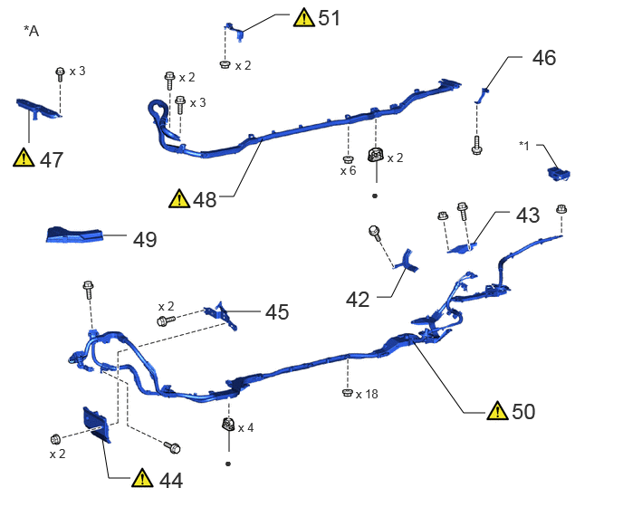
| Procedure | Part Name Code |
|
|
|
|
|---|---|---|---|---|---|
| 42 | WIRE HARNESS CLAMP BRACKET | - | - | - | - |
| 43 | WIRE HARNESS CLAMP BRACKET | - | - | - | - |
| 44 | NO. 9 WIRING HARNESS PROTECTOR | 82817J | ()
|
- | - |
| 45 | WIRE HARNESS CLAMP BRACKET | - | - | - | - |
| 46 | REAR TRACTION MOTOR WIRE CLAMP BRACKET | - | - | - | - |
| 47 | INVERTER TERMINAL COVER | G9223B | ()
|
- | - |
| 48 | NO. 2 BATTERY PACK WIRE | 821H3B | ()
|
- | - |
| 49 | NO. 3 RELAY BLOCK COVER | 82662C | - | - | - |
| 50 | FLOOR UNDER WIRE | 821H1 | ()
|
- | - |
| 51 | WIRE HARNESS CLAMP BRACKET | - | ()
|
- | - |
| *A | for RHD | - | - |
| *1 | CONNECTOR COVER | - | - |
| ● | Non-reusable part | - | - |
CAUTION / NOTICE / HINT
The necessary procedures (adjustment, calibration, initialization, or registration) that must be performed after parts are removed and installed, or replaced during floor under wire removal/installation are shown below.
| Replacement Part or Procedure | Necessary Procedure | Effect/Inoperative when not Performed | Link |
|---|---|---|---|
|
*: The vehicle height changes because of suspension or tire replacement. |
|||
| Disconnect cable from negative auxiliary battery terminal | Memorize steering angle neutral point | Parking assist monitor system | ()
|
| Panoramic view monitor system | ()
|
||
| Wheel alignment adjustment | Perform "Calibration" | Electronically controlled brake system malfunction | ()
|
·
Front bumper assembly (Including removal and installation) ·
Radiator grille assembly (Including removal and installation) |
·
Measurement of ultrasonic sensor detection angle ·
Ultrasonic sensor detection angle registration |
·
TOYOTA Parking assist- sensor system ·
Parking support brake system ·
Advanced park |
w/ Advanced Park:
( )
w/o Advanced Park: ( )
|
| Front television camera view adjustment | Panoramic view monior system | ()
|
|
| Front television camera assembly, front bumper assembly or radiator grille | ·
Television camera view adjustment
·
Rear television camera view adjustment (for Rear camera detection system) |
||
| Suspension, tires, etc.* | ·
Measurement of ultrasonic sensor detection angle ·
Ultrasonic sensor detection angle registration |
·
Parking support brake system ·
Advanced park |
w/ Advanced Park:
( )
w/o Advanced Park: ( )
|
| Rear television camera assembly optical axis (Back camera position setting) | Parking assist monitor system | ()
|
|
·
Parking assist ECU initialization ·
Adjust steering angle ·
Rear television camera view adjustment (for Rear camera detection system) |
Panoramic view monitor system | ()
|
|
| Perform headlight ECU sub-assembly LH initialization | Automatic headlight beam level control system | ()
|
|
·
Rear disc (Including removal and installation) ·
Parking brake shoe (Including removal and installation) ·
Parking brake actuator assembly with bracket (Removed and installed) |
Parking brake bedding | Electric parking brake system | ()
|
- CAUTION:
- ·
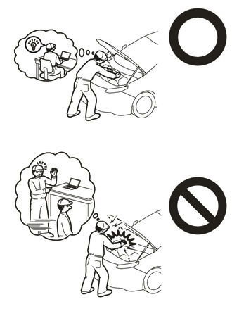
·Orange wire harnesses and connectors indicate high-voltage circuits. To prevent electric shock, always follow the procedure described in the repair manual.
Click hereEngine / Hybrid System>HYBRID / BATTERY CONTROL>HYBRID CONTROL SYSTEM>PRECAUTION
·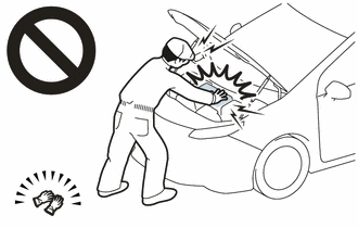
To prevent electric shock, wear insulated gloves when working on wire harnesses and components of the high voltage system.
- HINT:
-
When the cable is disconnected/reconnected to the auxiliary battery terminal, systems temporarily stop operating. However, each system has a function that completes learning the first time the system is used.
- ·
Learning completes when vehicle is driven
Effect/Inoperative Function When Necessary Procedures are not Performed Necessary Procedures Link Lane tracing assist system Drive the vehicle straight ahead at 35 km/h (22 mph) or more for 5 seconds or more. ( )
Pre-collision system Adaptive high beam system
- ·
Learning completes when vehicle is operated normally
Effect/Inoperative Function When Necessary Procedures are not Performed Necessary Procedures Link Air conditioning system After the ignition switch is turned to ON, the servo motor and expansion valve standard position is recognized. -
PROCEDURE

 1. CAUTIONS FOR COMPRESSED HYDROGEN GAS
|
|
Click here()
|
58404B
2.REMOVE REAR NO. 4 FLOOR BOARD SUB-ASSEMBLY
58403L
3.REMOVE REAR NO. 3 FLOOR BOARD SUB-ASSEMBLY
58402K
4.REMOVE NO. 2 FLOOR BOARD SUB-ASSEMBLY
|
|
Click here()
|
58401M
5.REMOVE NO. 1 FLOOR BOARD SUB-ASSEMBLY
|
|
Click here()
|
57628E
6.REMOVE REAR FLOOR SIDE MEMBER COVER LH
57627G
7.REMOVE REAR FLOOR SIDE MEMBER COVER RH
58398F
8.REMOVE NO. 1 FLOOR UNDER COVER
52383E
9.REMOVE NO. 1 DIFFERENTIAL SUPPORT PROTECTOR
52384C
10.REMOVE NO. 2 DIFFERENTIAL SUPPORT PROTECTOR
53661B
11.REMOVE REAR SUSPENSION BRACE COVER
17DB3
12.REMOVE NO. 3 FC EXHAUST PIPE
|
|
Click here()
|
13. PRESSURE RELEASE OPERATION
|
|
Click here()
|
G3834
14.REMOVE SERVICE PLUG GRIP
53292A
15.REMOVE UPPER RADIATOR SUPPORT SEAL
53291B
16.REMOVE RADIATOR COVER PLATE
53295
17.REMOVE LOWER RADIATOR AIR DEFLECTOR
55708
18.REMOVE COWL TOP VENTILATOR LOUVER SUB-ASSEMBLY
1A906
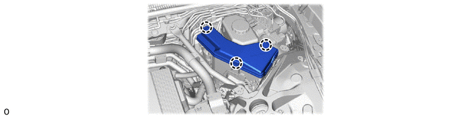
19.REMOVE FC STACK COVER SUB-ASSEMBLY
G9200A
20.DISCONNECT FC CONVERTER POWER OUTLET CABLE (INVERTER WITH CONVERTER ASSEMBLY)
|
|
Click here()
|
21.REMOVE CONNECTOR COVER ASSEMBLY
|
|
Click here()
|
22.CHECK TERMINAL VOLTAGE
|
|
Click here()
|
23.INSTALL CONNECTOR COVER ASSEMBLY
|
|
Click here()
|
821H3A
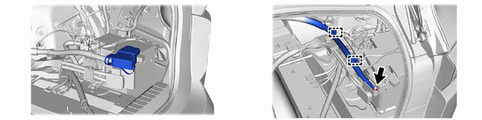
24.REMOVE NO. 1 BATTERY PACK WIRE
|
|
|
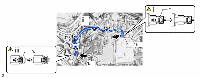
| *a | Connector A | *b | Connector B |
| *c | Green-colored Lock | - | - |

|
Slide | - | - |
Using a screwdriver, slide the green-colored lock of the connector A as shown in the illustration to release it and disconnect the No. 1 battery pack wire.
Disengage the clamp.
Using a screwdriver, slide the green-colored lock of the connector B as shown in the illustration to release it and disconnect the No. 1 battery pack wire.
G9A84C
25.REMOVE NO. 4 FC JUNCTION CABLE BRACKET
|
|
|
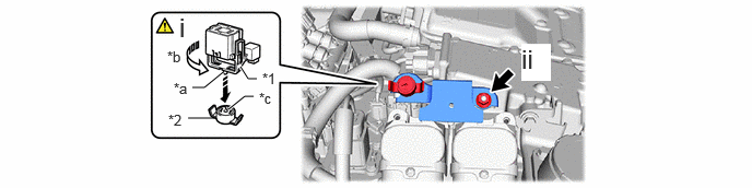
| *1 | Service Plug Grip | *2 | Battery Cover Lock Striker |
| *a | Projection | *b | Turn |
| *c | Button | - | - |
Using the service plug grip, remove the battery cover lock striker.
- HINT:
-
Insert the projection of the service plug grip and turn the button of the battery cover lock striker counterclockwise to release the lock.
Remove the nut and No. 4 FC junction cable bracket.
821H1
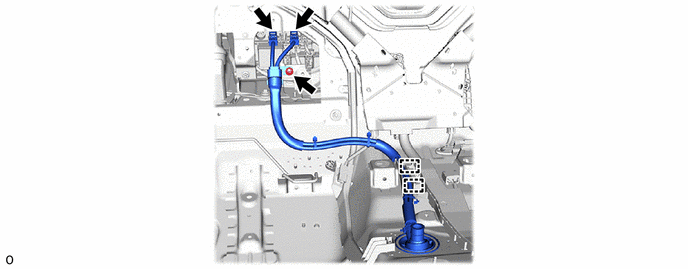
26.DISCONNECT FLOOR UNDER WIRE
|
|
|
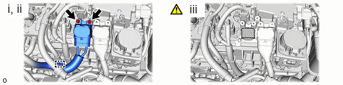
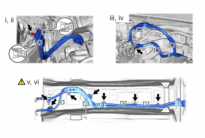
Disengage the clamp.
Remove the 2 bolts and disconnect the floor under wire from the FC stack assembly.
Protect the openings of the FC stack assembly with protective tape (non-residue type) to prevent the entry of foreign matter or water.
77A10
27.REMOVE NO. 1 HYDROGEN TANK ASSEMBLY
77A20
28.REMOVE NO. 2 HYDROGEN TANK ASSEMBLY
77A30
29.REMOVE NO. 3 HYDROGEN TANK ASSEMBLY
51206A
30.REMOVE REAR SUSPENSION MEMBER SUB-ASSEMBLY
31.REMOVE FC CONVERTER WITH FC STACK ASSEMBLY
64701
32.REMOVE LUGGAGE COMPARTMENT MAT SUB-ASSEMBLY
64715D
33.REMOVE LUGGAGE COMPARTMENT TRIM COVER LH
75201A
34.REMOVE TOOL BOX
64075B
35.REMOVE FRONT LUGGAGE COMPARTMENT TRIM COVER
58387
36.REMOVE REAR FLOOR FINISH PLATE
64722
37.REMOVE LUGGAGE COMPARTMENT TRIM COVER INNER LH
64721
38.REMOVE LUGGAGE COMPARTMENT TRIM COVER INNER RH
39.REMOVE BENCH TYPE REAR SEATBACK ASSEMBLY
64273D
40.REMOVE NO. 1 ROOM PARTITION PAD
58516A
41.REMOVE NO. 6 FLOOR MAT
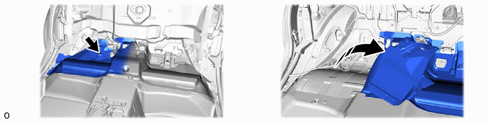
42.REMOVE WIRE HARNESS CLAMP BRACKET
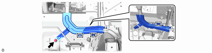
43.REMOVE WIRE HARNESS CLAMP BRACKET
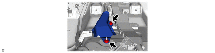
82817J
44.REMOVE NO. 9 WIRING HARNESS PROTECTOR
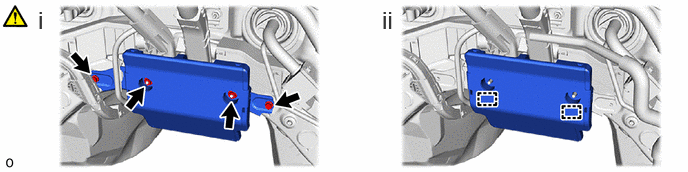
Remove the 2 nuts and 2 bolts and raise the No. 9 wire harness protector and wire harness clamp bracket.
Disengage the clamp and remove the No. 9 wiring harness protector from the wiring harness clamp bracket.
45.REMOVE WIRE HARNESS CLAMP BRACKET
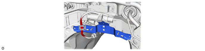
46.REMOVE REAR TRACTION MOTOR WIRE CLAMP BRACKET
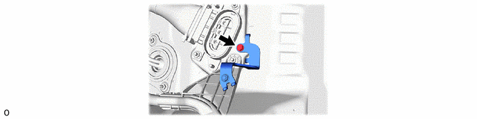
G9223B
47.REMOVE INVERTER TERMINAL COVER
|
|
Click here()
|
821H3B
48.REMOVE NO. 2 BATTERY PACK WIRE
|
|
|
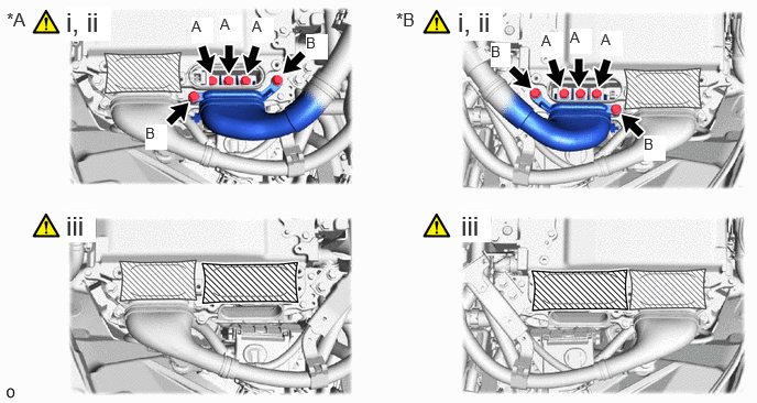
| *A | for LHD | *B | for RHD |
Using an insulated tool, remove the 3 bolts (A).
Using an insulated tool, remove the 2 bolts (B), and disconnect the No. 2 battery pack wire from the inverter with converter assembly.
- NOTICE:
- ·
Do not allow any foreign matter or water to enter the inverter with converter assembly.
·Do not touch the connector waterproofing rubber or terminals.
·Do not damage the terminals, connector housings or inverter with converter assembly during disconnection.
·Insulate the disconnected terminals with insulating tape.
·Cover the hole where the cable was connected with tape (non-residue type) or equivalent to prevent entry of foreign matter.
Protect the openings of the inverter with converter assembly with protective tape (non-residue type) to prevent the entry of foreign matter or water.
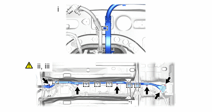
| *1 | Stud Clamp | - | - |
Disengage the clamp.
Remove the 6 nuts and 2 stud clamps.
- HINT:
-
When removing the stud clamp, break the claw on the stud clamp. The stud clamp cannot be reused.
Disengage the clamp and remove the No. 2 battery pack wire.
82662C
49.REMOVE NO. 3 RELAY BLOCK COVER
821H1
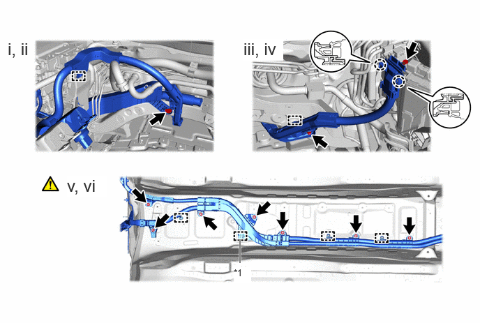
50.REMOVE FLOOR UNDER WIRE
|
|
|
for LHD:
| *1 | Stud Clamp | - | - |
Remove the bolt.
Disengage the clamp.
Remove the 2 bolts.
Disengage the claw, clamp and disconnect the floor under wire from the relay block.
Remove the 7 nuts and stud clamp.
- HINT:
-
When removing the stud clamp, break the claw on the stud clamp. The stud clamp cannot be reused.
Disengage the clamp.
for RHD:
| *1 | Stud Clamp | - | - |
Remove the bolt.
Disengage the claw and disconnect the floor under wire from the relay block.
Remove the bolt.
Disengage the clamp.
Remove the 7 nuts and stud clamp.
- HINT:
-
When removing the stud clamp, break the claw on the stud clamp. The stud clamp cannot be reused.
Disengage the clamp.
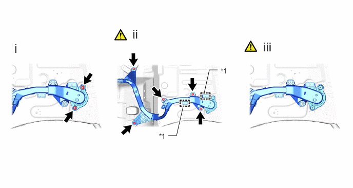
| *1 | Stud Clamp | - | - |
Remove the 2 nuts
Remove the 5 nuts and 2 stud clamps.
- HINT:
-
When removing the stud clamp, break the claw on the stud clamp. The stud clamp cannot be reused.
Disengage the grommet and pull out the floor under wire from the floor panel hole.
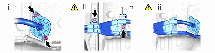
| *1 | Stud Clamp | - | - |
Remove the 2 nuts
Remove the 2 nuts and stud clamp.
- HINT:
-
When removing the stud clamp, break the claw on the stud clamp. The stud clamp cannot be reused.
Disengage the grommet and pull out the floor under wire from the floor panel hole.
51.REMOVE WIRE HARNESS CLAMP BRACKET
|
|
|