EC6D MANUAL TRANSMISSION / TRANSAXLE MANUAL TRANSAXLE ASSEMBLY(When Using the Engine Support Bridge) INSTALLATION
CAUTION / NOTICE / HINT
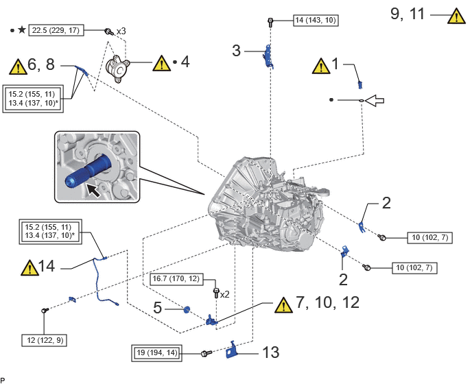
| Procedure | Part Name Code | 
|

|

|
|
|---|---|---|---|---|---|
| 1 | TRANSMISSION CASE PLUG ASSEMBLY | 35150D | ( ) |
- | - |
| 2 | WIRE HARNESS CLAMP BRACKET | - | - | - | - |
| 3 | HEATER BRACKET | 87121V | - | - | - |
| 4 | CLUTCH RELEASE CYLINDER WITH BEARING ASSEMBLY | 31400 | ()
|
- | - |
| 5 | CLUTCH TUBE BOOT | 31126B | - | - | - |
| 6 | TEMPORARILY INSTALL BLEEDER CLUTCH RELEASE TUBE | 31483 | ()
|
- | - |
| 7 | TEMPORARILY INSTALL CLUTCH RELEASE BLEEDER SUB-ASSEMBLY | 31407B | ()
|
- | - |
| 8 | FULLY TIGHTEN BLEEDER CLUTCH RELEASE TUBE | 31483 | ()
|
- | - |
| 9 | APPLY GREASE | - | ()
|
- | - |
| 10 | REMOVE CLUTCH RELEASE BLEEDER SUB-ASSEMBLY | 31407B | ()
|
- | - |
| 11 | INSPECT CLUTCH PIPE LINE | - | ()
|
- | - |
| 12 | INSTALL CLUTCH RELEASE BLEEDER SUB-ASSEMBLY | 31407B | ()
|
- | - |
| 13 | CLUTCH FLEXIBLE HOSE BRACKET | 31484 | - | - | - |
| 14 | CLUTCH RELEASE CYLINDER TO FLEXIBLE HOSE TUBE | 31482 | ()
|
- | - |

|
Tightening torque for "Major areas involving basic vehicle performance such as moving/turning/stopping": N*m (kgf*cm, ft.*lbf) | 
|
N*m (kgf*cm, ft.*lbf): Specified torque |
| * | For use with a union nut wrench | ● | Non-reusable part |

|
Clutch spline grease | 
|
Gear oil |
| ★ | Precoated part | - | - |
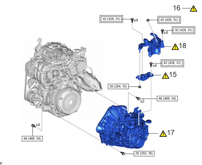
| Procedure | Part Name Code |
|
|
|
|
|---|---|---|---|---|---|
| 15 | ENGINE MOUNTING BRACKET LH | 12325A | ()
|
- | - |
| 16 | SUPPORT MANUAL TRANSAXLE ASSEMBLY | 30300 | ()
|
- | - |
| 17 | INSTALL MANUAL TRANSAXLE ASSEMBLY | 30300 | ()
|
- | - |
| 18 | ENGINE MOUNTING INSULATOR LH | 12372A | ()
|
- | - |
|
|
Tightening torque for "Major areas involving basic vehicle performance such as moving/turning/stopping": N*m (kgf*cm, ft.*lbf) |
|
N*m (kgf*cm, ft.*lbf): Specified torque |
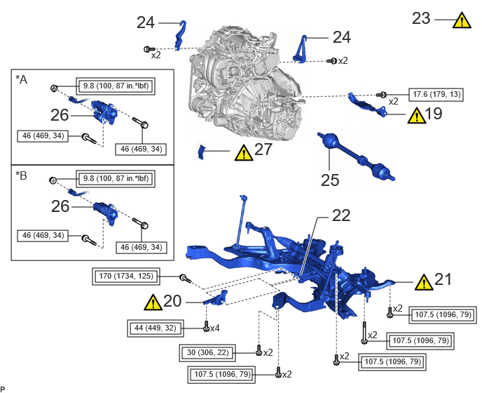
| Procedure | Part Name Code |
|
|
|
|
|---|---|---|---|---|---|
| 19 | DRIVE SHAFT HEAT INSULATOR SUB-ASSEMBLY | 43409E | ()
|
- | - |
| 20 | NO. 2 ENGINE MOVING CONTROL ROD | 12364B | ()
|
- | - |
| 21 | FRONT SUSPENSION CROSSMEMBER SUB-ASSEMBLY | 51201 | ()
|
- | - |
| 22 | ENGINE MOVING CONTROL ROD | 12363A | - | - | - |
| 23 | ENGINE SUPPORT BRIDGE | - | ()
|
- | - |
| 24 | ENGINE HANGERS | - | - | - | - |
| 25 | FRONT DRIVE SHAFT ASSEMBLY | - | - | - | - |
| 26 | STARTER ASSEMBLY | 28100 | - | - | - |
| 27 | FLYWHEEL HOUSING SIDE COVER | 11363A | ()
|
- | - |
| *A | w/ Stop and Start System | *B | w/o Stop and Start System |
|
|
Tightening torque for "Major areas involving basic vehicle performance such as moving/turning/stopping": N*m (kgf*cm, ft.*lbf) |
|
N*m (kgf*cm, ft.*lbf): Specified torque |
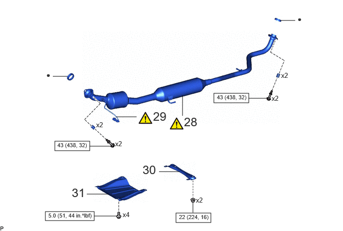
| Procedure | Part Name Code |
|
|
|
|
|---|---|---|---|---|---|
| 28 | FRONT EXHAUST PIPE ASSEMBLY | 17410 | ()
|
- | - |
| 29 | NO. 2 AIR FUEL RATIO SENSOR | 89467C | ()
|
- | - |
| 30 | CENTER NO. 1 FLOOR BRACE | 57543C | - | - | - |
| 31 | CENTER NO. 4 ENGINE UNDER COVER | 51447D | - | - | - |
|
|
N*m (kgf*cm, ft.*lbf): Specified torque | ● | Non-reusable part |
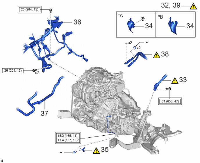
| Procedure | Part Name Code |
|
|
|
|
|---|---|---|---|---|---|
| 32 | ALIGN FRONT WHEELS FACING STRAIGHT AHEAD | - | ()
|
- | - |
| 33 | NO. 2 STEERING INTERMEDIATE SHAFT ASSEMBLY | 45260 | ()
|
- | - |
| 34 | COLUMN HOLE COVER SILENCER SHEET | 45259A | - | - | - |
| 35 | CLUTCH HOSE | 31418 | ()
|
- | - |
| 36 | ENGINE WIRE | 82121 | - | - | - |
| 37 | NO. 3 WATER BY-PASS HOSE ASSEMBLY | 16290F | - | - | - |
| 38 | CONNECT TRANSMISSION CONTROL CABLE ASSEMBLY | 33820B | ()
|
- | - |
| 39 | ADJUST TRANSMISSION CONTROL CABLE ASSEMBLY | 33820B | ()
|
- | - |
| *A | for LHD | *B | for RHD |
|
|
Tightening torque for "Major areas involving basic vehicle performance such as moving/turning/stopping": N*m (kgf*cm, ft.*lbf) |
|
N*m (kgf*cm, ft.*lbf): Specified torque |
| * | For use with a union nut wrench | ● | Non-reusable part |
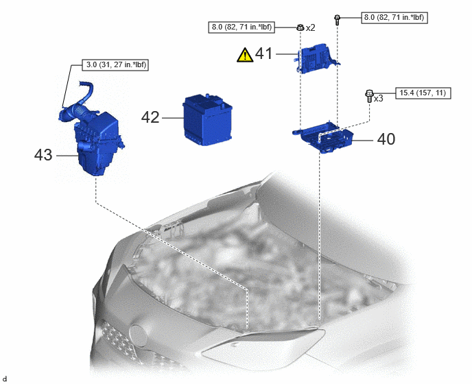
| Procedure | Part Name Code |
|
|
|
|
|---|---|---|---|---|---|
| 40 | BATTERY CLAMP SUB-ASSEMBLY | 74404A | - | - | - |
| 41 | ECM | 89661 | ()
|
- | - |
| 42 | AUXILIARY BATTERY | 28800 | - | - | - |
| 43 | AIR CLEANER ASSEMBLY WITH AIR CLEANER HOSE | - | - | - | - |
|
|
N*m (kgf*cm, ft.*lbf): Specified torque | - | - |
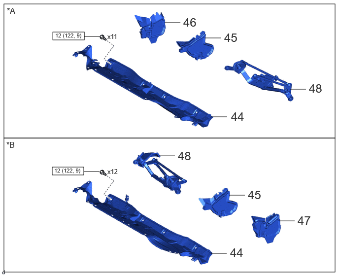
| Procedure | Part Name Code |
|
|
|
|
|---|---|---|---|---|---|
| 44 | OUTER COWL TOP PANEL SUB-ASSEMBLY | 55701J | - | - | - |
| 45 | FRONT NO. 1 VENTILATOR SEAL | 55815E | - | - | - |
| 46 | WATER GUARD PLATE RH | 55734A | - | - | - |
| 47 | WATER GUARD PLATE LH | 55735A | - | - | - |
| 48 | WINDSHIELD WIPER MOTOR AND LINK ASSEMBLY | - | - | - | - |
| *A | for LHD | *B | for RHD |
|
|
N*m (kgf*cm, ft.*lbf): Specified torque | - | - |
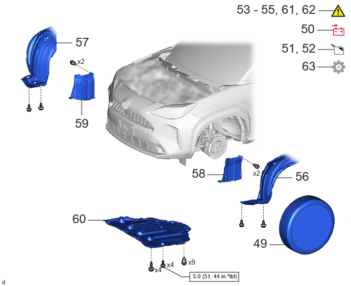
| Procedure | Part Name Code |
|
|
|
|
|---|---|---|---|---|---|
| 49 | FRONT WHEELS | - | - | - | - |
| 50 | CONNECT CABLE TO NEGATIVE AUXILIARY BATTERY TERMINAL | - | - | - | - |
| 51 | ADD MANUAL TRANSAXLE OIL | - | - | ()
|
- |
| 52 | BLEED CLUTCH LINE | - | - | ()
|
- |
| 53 | INSPECT MANUAL TRANSAXLE OIL | - | ()
|
- | - |
| 54 | INSPECT FOR MANUAL TRANSAXLE OIL LEAK | - | ()
|
- | - |
| 55 | INSPECT FOR EXHAUST GAS LEAK | - | ()
|
- | - |
| 56 | FRONT FENDER LINER LH | 53876A | - | - | - |
| 57 | FRONT FENDER LINER RH | 53875A | - | - | - |
| 58 | ENGINE UNDER COVER LH | 51442C | - | - | - |
| 59 | ENGINE UNDER COVER RH | 51441C | - | - | - |
| 60 | NO. 1 ENGINE UNDER COVER ASSEMBLY | 51410 | - | - | - |
| 61 | CHECK FOR SPEED SENSOR SIGNAL | - | ()
|
- | - |
| 62 | INSPECT AND ADJUST FRONT WHEEL ALIGNMENT | - | ()
|
- | - |
| 63 | INITIALIZATION AFTER RECONNECTING AUXILIARY BATTERY TERMINAL | - | - | - | ()
|
|
|
N*m (kgf*cm, ft.*lbf): Specified torque | - | - |
CAUTION / NOTICE / HINT
- NOTICE:
-
When the manual transaxle assembly is removed, be sure to use a new clutch release cylinder with bearing assembly and new installation bolts. Removal of the manual transaxle assembly allows the compressed clutch release cylinder with bearing assembly to return to its original position. Dust from the moving section may damage the seal of the clutch release cylinder with bearing assembly, possibly causing clutch fluid leaks.
PROCEDURE

 35150D
1.INSTALL TRANSMISSION CASE PLUG ASSEMBLY
|
|
Click here()
|
2.INSTALL WIRE HARNESS CLAMP BRACKET
87121V
3.INSTALL HEATER BRACKET
31400
4.INSTALL CLUTCH RELEASE CYLINDER WITH BEARING ASSEMBLY
|
|
Click here()
|
31126B
5.INSTALL CLUTCH TUBE BOOT
31483
6.TEMPORARILY INSTALL BLEEDER CLUTCH RELEASE TUBE
|
|
Click here()
|
31407B
7.TEMPORARILY INSTALL CLUTCH RELEASE BLEEDER SUB-ASSEMBLY
|
|
Click here()
|
31483
8.FULLY TIGHTEN BLEEDER CLUTCH RELEASE TUBE
|
|
Click here()
|
9.APPLY GREASE
|
|
Click here()
|
31407B
10.REMOVE CLUTCH RELEASE BLEEDER SUB-ASSEMBLY
|
|
Click here()
|
11.INSPECT CLUTCH PIPE LINE
|
|
Click here()
|
31407B
12.INSTALL CLUTCH RELEASE BLEEDER SUB-ASSEMBLY
|
|
Click here()
|
31484
13.INSTALL CLUTCH FLEXIBLE HOSE BRACKET
31482
14.INSTALL CLUTCH RELEASE CYLINDER TO FLEXIBLE HOSE TUBE
|
|
Click here()
|
12325A
15.INSTALL ENGINE MOUNTING BRACKET LH
|
|
Click here()
|
30300
16.SUPPORT MANUAL TRANSAXLE ASSEMBLY
|
|
Click here()
|
30300
17.INSTALL MANUAL TRANSAXLE ASSEMBLY
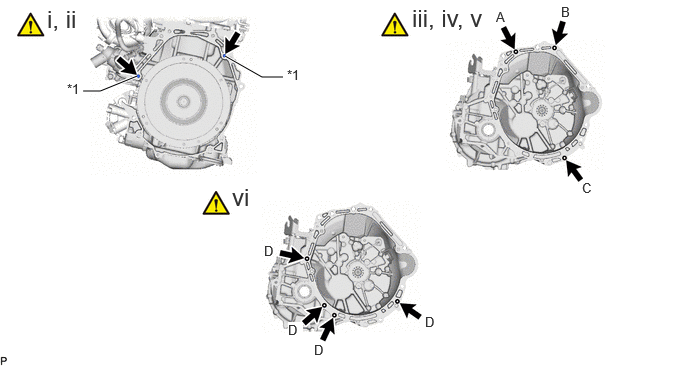
| *1 | Knock Pin | - | - |
Check that the 2 knock pins are installed on the engine assembly before installing the manual transaxle assembly.
Align the input shaft with the clutch disc and install the manual transaxle assembly to the engine assembly.
- NOTICE:
- ·
Make sure that the wire harness or similar items are not pinched between the contact surfaces.
·Do not forcibly pry on the manual transaxle assembly when installing it to the engine assembly.
·Do not apply excessive force to the manual transaxle assembly as this will break the input shaft.
·Make sure that the knock pins fit securely into the holes when installing the manual transaxle assembly to the engine assembly.
·Make sure that the contact surfaces of the engine assembly and manual transaxle assembly are flat against each other before tightening the bolts.
Temporarily install the bolt (A).
- HINT:
-
Bolt (A): Install from the manual transaxle assembly side.
Install the bolt (B), then fully tighten the bolt (A).
- Torque:
- 46 N*m (469 kgf*cm, 34 ft.*lbf)
- HINT:
-
Bolt (B): Install from the manual transaxle assembly side.
Install the bolt (C).
- Torque:
- 25 N*m (255 kgf*cm, 18 ft.*lbf)
- HINT:
-
Bolt (C): Install from the manual transaxle assembly side.
Install the 4 bolts (D).
- Torque:
- 46 N*m (469 kgf*cm, 34 ft.*lbf)
- HINT:
-
Bolt (D): Install from the engine assembly side.
12372A
18.INSTALL ENGINE MOUNTING INSULATOR LH
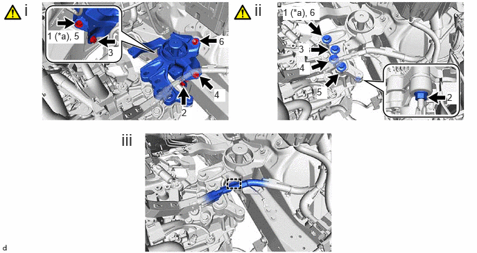
| *a | Temporarily Tighten | - | - |
Install the engine mounting insulator LH to the vehicle body with the 4 bolts and nut in the order shown in the illustration.
- Torque:
- 42 N*m (428 kgf*cm, 31 ft.*lbf)
Install the engine mounting insulator LH to the manual transaxle assembly with the 4 bolts and nut in the order shown in the illustration.
- Torque:
- for Bolt : 42 N*m (428 kgf*cm, 31 ft.*lbf)
- for Nut : 20 N*m (204 kgf*cm, 15 ft.*lbf)
Engage the clamp to install the engine wire to the engine mounting insulator LH.
43409E
19.INSTALL DRIVE SHAFT HEAT INSULATOR SUB-ASSEMBLY
|
|
Click here()
|
12364B
20.INSTALL NO. 2 ENGINE MOVING CONTROL ROD
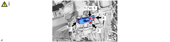
| *a | Temporarily Tighten | - | - |
Install the No. 2 engine moving control rod to the manual transaxle assembly with the 4 bolts in the order shown in the illustration.
- Torque:
- 44 N*m (449 kgf*cm, 32 ft.*lbf)
51201
21.INSTALL FRONT SUSPENSION CROSSMEMBER SUB-ASSEMBLY
|
|
Click here()
|
12363A
22.CONNECT ENGINE MOVING CONTROL ROD
23.REMOVE ENGINE SUPPORT BRIDGE
|
|
|
24.REMOVE ENGINE HANGERS
25.INSTALL FRONT DRIVE SHAFT ASSEMBLY
28100
26.INSTALL STARTER ASSEMBLY
w/ Stop and Start System:
Click hereEngine / Hybrid System>M15A-FKS (STARTING)>STARTER (w/ Stop And Start System)>INSTALLATION
w/o Stop and Start System:
Click hereEngine / Hybrid System>M15A-FKS (STARTING)>STARTER (w/o Stop And Start System)>INSTALLATION
11363A
27.INSTALL FLYWHEEL HOUSING SIDE COVER
|
|
·
w/ Stop and Start System: Click here( ·
w/o Stop and Start System: Click here( |
17410
28.INSTALL FRONT EXHAUST PIPE ASSEMBLY
|
|
Click here()
|
89467C
29.CONNECT NO. 2 AIR FUEL RATIO SENSOR
|
|
Click here()
|
57543C
30.INSTALL CENTER NO. 1 FLOOR BRACE
51447D
31.INSTALL CENTER NO. 4 ENGINE UNDER COVER
32. ALIGN FRONT WHEELS FACING STRAIGHT AHEAD
|
|
Click here()
|
45260
33.CONNECT NO. 2 STEERING INTERMEDIATE SHAFT ASSEMBLY
|
|
Click here()
|
45259A
34.INSTALL COLUMN HOLE COVER SILENCER SHEET
31418
35.CONNECT CLUTCH HOSE
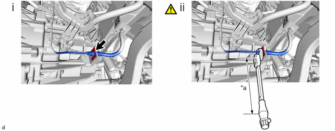
| *a | Torque Wrench Fulcrum Length | - | - |
Connect the clutch hose to the clutch flexible hose bracket with a new clip.
Using a 10 mm union nut wrench, connect the clutch release cylinder to flexible hose tube to the clutch hose.
- Torque:
- Specified tightening torque : 15.2 N*m (155 kgf*cm, 11 ft.*lbf)
- HINT:
- ·
Calculate the torque wrench reading when changing the fulcrum length of the torque wrench.
Click hereGeneral>INTRODUCTION>REPAIR INSTRUCTION>PRECAUTION
·When using a 10 mm union nut wrench (fulcrum length of 22 mm (0.866 in.)) + torque wrench (fulcrum length of 162 mm (6.38 in.)): 13.4 N*m (137 kgf*cm, 10 ft.*lbf)
82121
36.CONNECT ENGINE WIRE
16290F
37.INSTALL NO. 3 WATER BY-PASS HOSE ASSEMBLY
33820B
38.CONNECT TRANSMISSION CONTROL CABLE ASSEMBLY
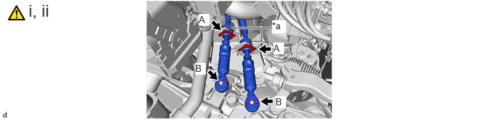
| *a | Paint Mark | - | - |
Install the transmission control cable assembly to the control cable bracket assembly with 2 new clips (A).
- NOTICE:
-
Make sure that the paint marks on the transmission control cable assembly are aligned with the slits in the control cable bracket assembly before installing the clips.
Connect the transmission control cable assembly to the manual transaxle assembly with the 2 clips (B).
33820B
39.ADJUST TRANSMISSION CONTROL CABLE ASSEMBLY
74404A
40.INSTALL BATTERY CLAMP SUB-ASSEMBLY
89661
41.INSTALL ECM
|
|
Click here()
|
28800
42.INSTALL AUXILIARY BATTERY
43.INSTALL AIR CLEANER ASSEMBLY WITH AIR CLEANER HOSE
w/ Stop and Start System:
Click hereEngine / Hybrid System>M15A-FKS (STARTING)>STARTER (w/ Stop And Start System)>INSTALLATION
w/o Stop and Start System:
Click hereEngine / Hybrid System>M15A-FKS (STARTING)>STARTER (w/o Stop And Start System)>INSTALLATION
55701J
44.INSTALL OUTER COWL TOP PANEL SUB-ASSEMBLY
55815E
45.INSTALL FRONT NO. 1 VENTILATOR SEAL
55734A
46.INSTALL WATER GUARD PLATE RH (for LHD)
55735A
47.INSTALL WATER GUARD PLATE LH (for RHD)
48.INSTALL WINDSHIELD WIPER MOTOR AND LINK ASSEMBLY
49.INSTALL FRONT WHEELS
50.CONNECT CABLE TO NEGATIVE AUXILIARY BATTERY TERMINAL
51.ADD MANUAL TRANSAXLE OIL
52.BLEED CLUTCH LINE
Click hereDrivetrain>CLUTCH>CLUTCH SYSTEM>BLEEDING
53.INSPECT MANUAL TRANSAXLE OIL
54.INSPECT FOR MANUAL TRANSAXLE OIL LEAK
55.INSPECT FOR EXHAUST GAS LEAK
53876A
56.INSTALL FRONT FENDER LINER LH
53875A
57.INSTALL FRONT FENDER LINER RH
51442C
58.INSTALL ENGINE UNDER COVER LH
51441C
59.INSTALL ENGINE UNDER COVER RH
51410
60.INSTALL NO. 1 ENGINE UNDER COVER ASSEMBLY
61.CHECK FOR SPEED SENSOR SIGNAL
62.INSPECT AND ADJUST FRONT WHEEL ALIGNMENT
63. INITIALIZATION AFTER RECONNECTING AUXILIARY BATTERY TERMINAL
- HINT:
-
When disconnecting and reconnecting the auxiliary battery, there is an automatic learning function that completes learning when the respective system is used.
-
Click hereGeneral>SETUP>WHEN DISCONNECTING OR RECONNECTING BATTERY TERMINAL>AUTOMATIC LEARNING CHART