Brake Booster Removal and Installation
Precautions: Precautions for Brake Service · Precautions for Brakes · General safety (00)
NOTICE:
The brake master cylinder and brake booster will lose their original performance if they are disassembled and reassembled.
If any faulty condition is found in the brake master cylinder or brake booster, replace the part rather than trying to disassemble and repair it.
Removal
LHD
1)For D16AA model, remove the following parts.
•Battery: 
•Air cleaner assembly and air cleaner bracket:
•Air cleaner assembly and air cleaner bracket:
2)For K14C model, remove the following parts.
•Battery:
•Air cleaner assembly:
•Intercooler outlet hose No.2.
•Air cleaner assembly:
•Intercooler outlet hose No.2.
3)Remove brake master cylinder assembly from brake booster.
4)For ENG A-STOP model, disconnect brake booster pressure sensor connector.
5)Disconnect vacuum hose from brake booster.
6)Remove instrument panel undercover.
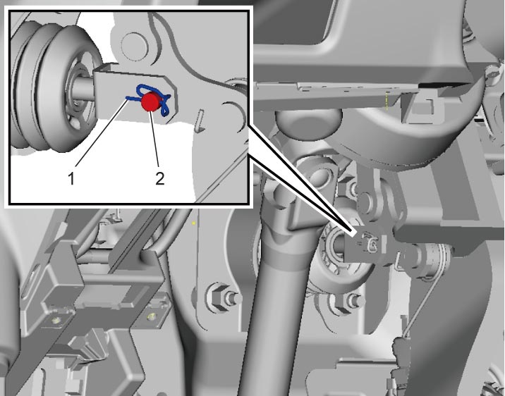
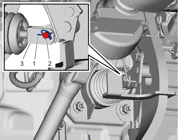
7)Remove clip (1) and clevis pin (2).

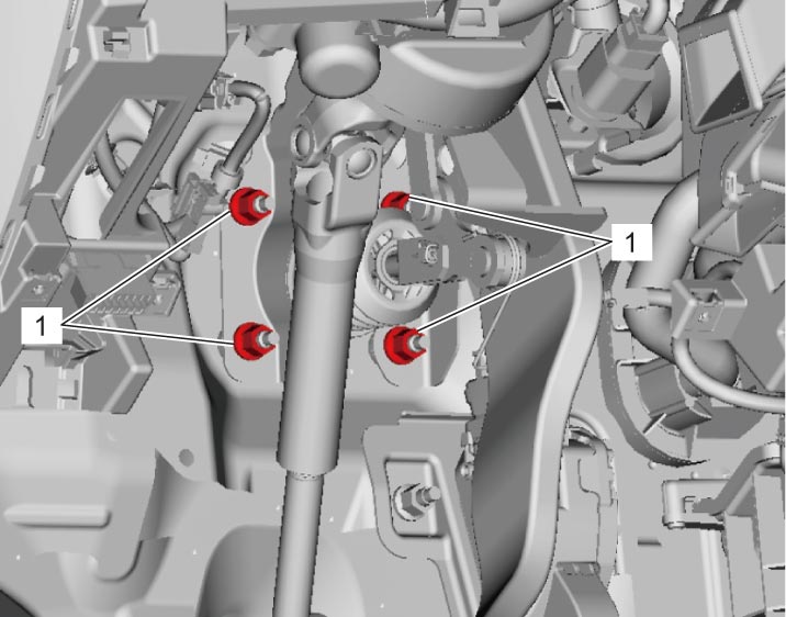
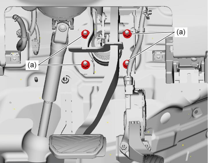
8)Remove brake booster nuts (1) and remove brake booster from dash panel.
9)Remove vacuum check valve (1) or brake booster pressure sensor (2) from brake booster (3).
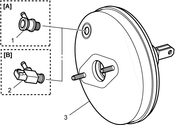
| [A]: | Non-ENG A-STOP model | [B]: | ENG A-STOP model |
RHD
1)Remove intake manifold.
•M16A model:
•K14C model:
•K14C model:
2)For D16AA model, remove engine assembly.
3)For A/C model, remove the following parts.
•HFO-1234yf model:
—Manual A/C type:
Inner heat exchanger pipe: .
—Automatic A/C type:
Inner heat exchanger pipe: .
•HFC-134A model:Inner heat exchanger pipe:
.—Automatic A/C type:
Inner heat exchanger pipe:
.
—Manual A/C type:
Suction pipe: .
—Automatic A/C type:
Suction pipe: .
Suction pipe:
.—Automatic A/C type:
Suction pipe:
.
4)Remove fuel pipe protector.
•M16A model:
•K14C model:
•K14C model:
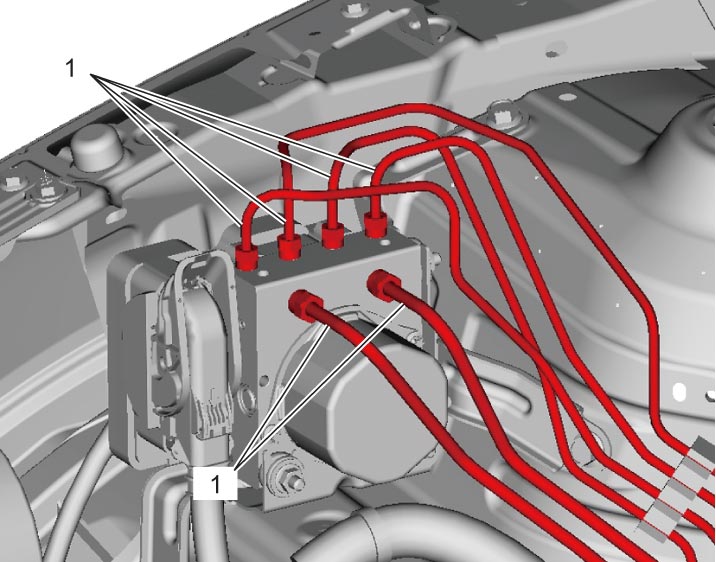
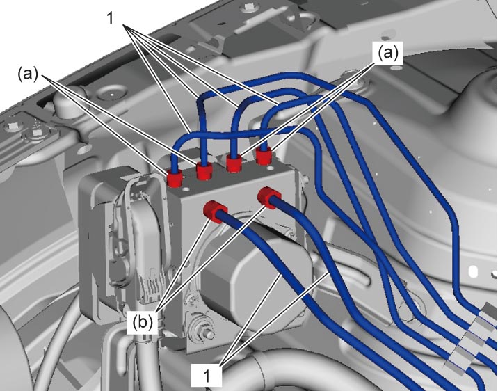
5)Disconnect brake pipes (1) from ESP® hydraulic unit / control module assembly using special tool.
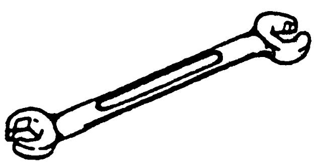
6)Remove brake master cylinder assembly from booster.
7)For ENG A-STOP model, disconnect brake booster pressure sensor connector.
8)Disconnect vacuum hose from brake booster.
9)Remove instrument panel undercover.
10)Remove clip (1) and clevis pin (2).
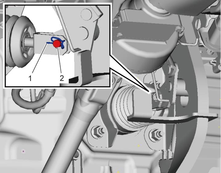
11)Remove brake booster nuts (1) and remove brake booster from dash panel.
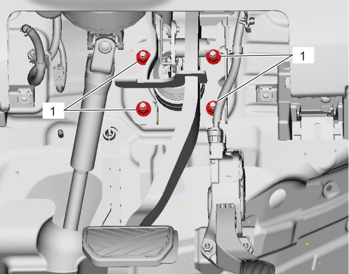
12)Remove vacuum check valve (1) or brake booster pressure sensor (2) from brake booster (3).
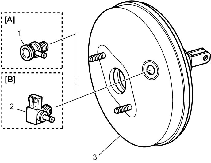
| [A]: | Non-ENG A-STOP model | [B]: | ENG A-STOP model |
Installation
LHD
1)Install vacuum check valve (1) or brake booster pressure sensor (2) to brake booster (3).
| [A]: | Non-ENG A-STOP model | [B]: | ENG A-STOP model |
2)Remove combination meter.
3)Loosen brake pedal bracket nut (1).
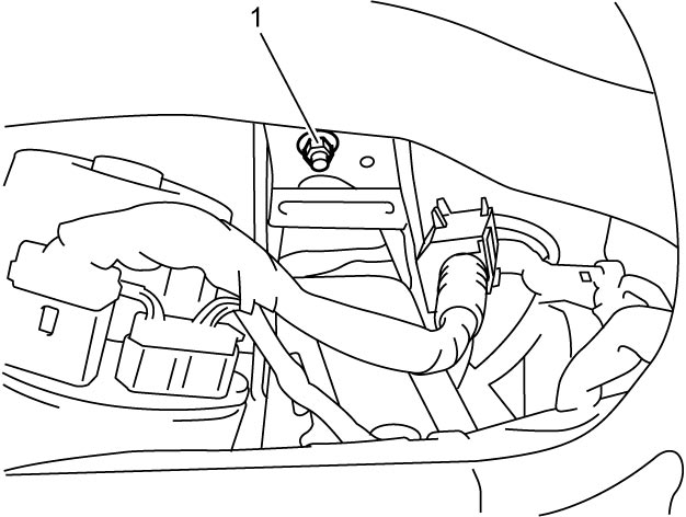
4)Install brake booster to dash panel with new gasket. Then connect clevis (3) to brake pedal arm with clevis pin (2) and new clip (1).

5)Tighten brake booster nuts to specified torque.
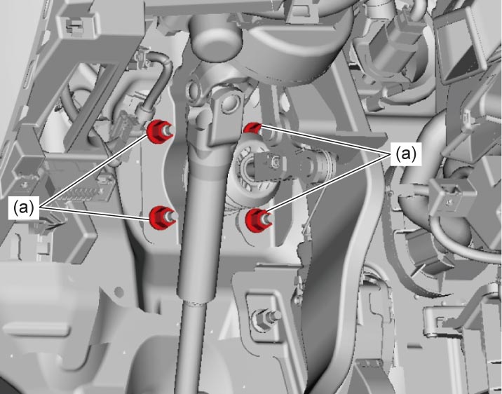
6)Tighten brake pedal bracket nut to specified torque.
7)Install instrument panel undercover.
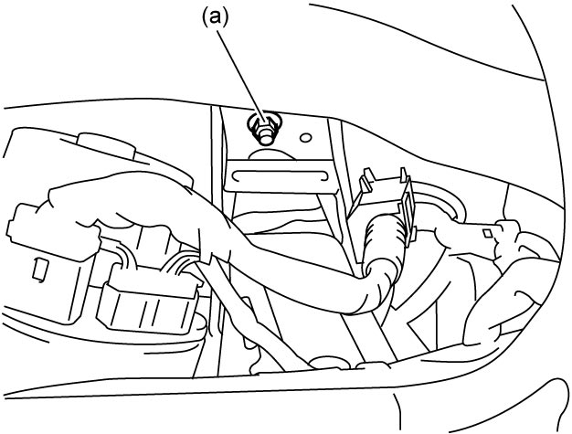
8)Install combination meter.
9)Connect vacuum hose to brake booster.
10)For ENG A-STOP model, connect brake booster pressure sensor connector.
11)Install brake master cylinder assembly to brake booster.
12)Bleed brake system.
13)Check installed parts for brake fluid leakage.
14)Check brake pedal for play.
15)Check that brake system operates properly without brake fluid leakage.
16)For D16AA model, install the following parts.
•Air cleaner assembly and air cleaner bracket:
•Battery:
•Battery:
17)For K14C model, install the following parts.
•Battery:
•Air cleaner assembly:
•Intercooler outlet hose No.2.
•Air cleaner assembly:
•Intercooler outlet hose No.2.
RHD
1)Install vacuum check valve (1) or brake booster pressure sensor (2) to brake booster (3).
| [A]: | Non-ENG A-STOP model | [B]: | ENG A-STOP model |
2)Remove combination meter.
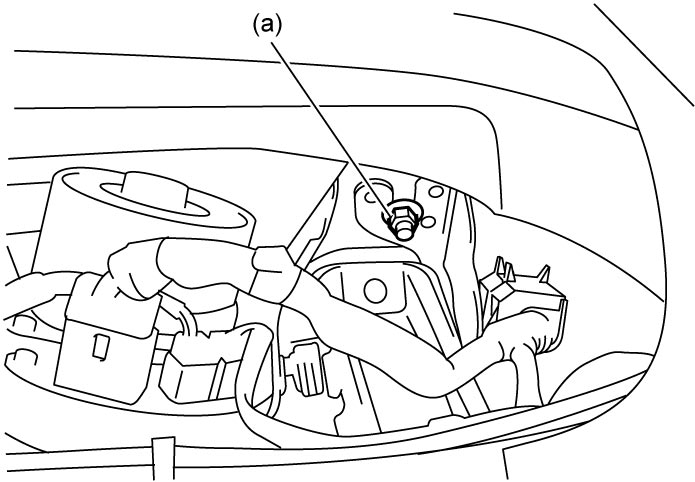
3)Loosen brake pedal bracket nut (1).
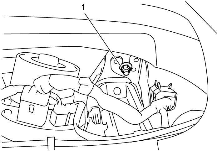
4)Install brake booster to dash panel with new gasket. Then connect clevis (3) to brake pedal arm with clevis pin (2) and new clip (1).
5)Tighten brake booster nuts to specified torque.
6)Install instrument panel undercover.
7)Tighten brake pedal bracket nut to specified torque.
8)Install combination meter.
9)Connect vacuum hose to brake booster.
10)For ENG A-STOP model, disconnect brake booster pressure sensor connector.
11)Install brake master cylinder assembly to brake booster.
12)Connect brake pipes (1) to ESP® hydraulic unit / control module assembly and tighten flare nuts to specified torque.
Brake pipe flare nut (M12) (b): 19 N·m (1.9 kgf-m, 14.0 lbf-ft)
Tightening torque
Brake pipe flare nut (M10) (a): 16 N·m (1.6 kgf-m, 12.0 lbf-ft)Brake pipe flare nut (M12) (b): 19 N·m (1.9 kgf-m, 14.0 lbf-ft)
13)For M16A model, install fuel pipe protector.
14)For A/C model, install the following parts.
•HFO-1234yf model:
—Manual A/C type:
Inner heat exchanger pipe: .
—Automatic A/C type:
Inner heat exchanger pipe: .
•HFC-134a model:Inner heat exchanger pipe:
.—Automatic A/C type:
Inner heat exchanger pipe:
.
—Manual A/C type:
Suction pipe: .
—Automatic A/C type:
Suction pipe: .
Suction pipe:
.—Automatic A/C type:
Suction pipe:
.
15)Install intake manifold.
•M16A model:
•K14C model:
•K14C model:
16)For D16AA model, install engine assembly.
17)Bleed brake system.
18)Check installed parts for brake fluid leakage.
19)Check brake pedal for play.
20)Check that brake system operates properly without brake fluid leakage.