1GD-FTV ENGINE MECHANICAL CAMSHAFT(w/ EGR Cooler) REMOVAL
CAUTION / NOTICE / HINT
The necessary procedures (adjustment, calibration, initialization, or registration) that must be performed after parts are removed, installed, or replaced during the camshaft removal/installation are shown below.
| Replacement Part or Procedure | Necessary Procedures | Effects/Inoperative when not Performed | Link |
|---|---|---|---|
| Battery terminal is disconnected/reconnected | Memorize steering angle neutral point | Parking assist monitor system | ( ) |
| Panoramic view monitor system | ()
|
||
| Replacement of injector assembly | ·
Injector compensation code registration ·
Pilot quantity learning |
Engine starting | ·
w/ DPF: ( ·
w/ Urea SCR System: ( ·
w/ EGR Cooler: ( |
·
Replacement of diesel throttle body assembly ·
Replacement of electric EGR control valve assembly |
Perform initialization | - | ·
w/ DPF: ( ·
w/ Urea SCR System: ( ·
w/ EGR Cooler: ( ·
w/ Exhaust Gas Temperature Sensor for EGR ( |
- HINT:
-
When the cable is disconnected / reconnected to the battery terminal, systems temporarily stop operating. However, each system has a function that completes learning the first time the system is used.
- ·
Learning completes when vehicle is driven
Effect/Inoperative when not Performed Necessary Procedures Link Stop and start system Drive the vehicle until stop and start control is permitted (approximately 5 to 60 minutes). ( )
Lane control system Drive the vehicle straight ahead at 15 km/h (10 mph) or more for 1 second or more. ( )
Pre-collision system
·Learning completes when vehicle is operated normally
Effect/Inoperative when not Performed Necessary Procedures Link Power slide door system Fully close the slide door by hand.
- HINT:
-
Initialization is not necessary if the above procedures are performed while the slide door is closed.
( )
Air conditioning system After the ignition switch is turned to ON, the servo motor standard position is recognized. -
- NOTICE:
- ·
When replacing the parts in the following chart (A), replace the No. 1 injection pipe sub-assembly, No. 2 injection pipe sub-assembly and/or fuel inlet pipe sub-assembly with new ones.
Replaced Parts (A) Pipes Requiring New Replacement Injector assembly (including shuffling the injector assemblies between the cylinders) ·No. 1 injection pipe sub-assembly
·No. 2 injection pipe sub-assembly
Supply pump assembly Fuel inlet pipe sub-assembly ·Common rail assembly
·Cylinder block sub-assembly
·Cylinder head sub-assembly
·Cylinder head gasket
·Timing chain case assembly
·No. 1 injection pipe sub-assembly
·No. 2 injection pipe sub-assembly
·Fuel inlet pipe sub-assembly
·After removing the No. 1 injection pipe sub-assembly, No. 2 injection pipe sub-assembly and/or fuel inlet pipe sub-assembly, clean them with a brush and compressed air.
·The injector assembly is a precision instrument. Do not use the injector assembly if it is struck or dropped.
·The supply pump assembly is a precision instrument. Do not use the supply pump assembly if it is struck or dropped.
·The common rail assembly is a precision instrument. Do not use the common rail assembly if it is struck or dropped.
·Hold the supply pump assembly itself during removal and installation. Do not hold the pre-stroke control valve or fuel pipe, etc.
·Hold the common rail assembly itself during removal and installation. Do not hold the pressure discharge valve or fuel pressure sensor, etc.
·Make sure foreign matter does not enter the fuel path.
PROCEDURE

 1. PRECAUTION
- NOTICE:
-
After turning the ignition switch off, waiting time may be required before disconnecting the cable from the battery terminal.
-
Click hereGeneral>SETUP>WHEN DISCONNECTING OR RECONNECTING BATTERY TERMINAL>BEFORE DISCONNECTING BATTERY
2.DISCONNECT CABLE FROM NEGATIVE BATTERY TERMINAL
51406A
3.REMOVE NO. 2 ENGINE UNDER COVER SUB-ASSEMBLY (w/ No. 2 Engine Under Cover Sub-assembly)
52618
4.REMOVE LOWER FRONT BUMPER ABSORBER
51405A
5.REMOVE NO. 1 ENGINE UNDER COVER SUB-ASSEMBLY
6.DRAIN ENGINE COOLANT
7.DRAIN ENGINE COOLANT (for Intercooler)
85110
8.REMOVE WINDSHIELD WIPER MOTOR ASSEMBLY
55701J
9.REMOVE OUTER COWL TOP PANEL SUB-ASSEMBLY
53106B
10.REMOVE RADIATOR COVER SUB-ASSEMBLY
12601B
11.REMOVE NO. 1 ENGINE COVER SUB-ASSEMBLY (for Water Cooled Type Intercooler)
16551C
12.DISCONNECT NO. 1 INTERCOOLER COOLING WATER HOSE (for Water Cooled Type Intercooler)
13.REMOVE NO. 2 INTERCOOLER COOLING WATER PIPE ASSEMBLY (for Water Cooled Type Intercooler)
17360E
14.REMOVE NO. 1 AIR TUBE ASSEMBLY (for Water Cooled Type Intercooler)
17030
15.REMOVE AIR HOSE ASSEMBLY (for Water Cooled Type Intercooler)
16278
16.REMOVE NO. 2 WATER BY-PASS PIPE (for Water Cooled Type Intercooler)
17940D
17.REMOVE INTERCOOLER ASSEMBLY (for Water Cooled Type Intercooler)
17751
18.REMOVE NO. 1 AIR CLEANER INLET
44360
19.DISCONNECT VANE PUMP OIL RESERVOIR ASSEMBLY
17030
20.REMOVE AIR HOSE ASSEMBLY
16470
21.REMOVE RADIATOR RESERVE TANK ASSEMBLY
16640
22.REMOVE INTERCOOLER RESERVE TANK ASSEMBLY (for Water Cooled Type Intercooler)
16571C
23.REMOVE NO. 1 RADIATOR HOSE
16552C
24.REMOVE NO.2 INTERCOOLER COOLING WATER HOSE (for Water Cooled Type Intercooler)
165A0
25.REMOVE NO.1 INTERCOOLER COOLING WATER HOSE ASSEMBLY (for Water Cooled Type Intercooler)
161B0
26.REMOVE ELECTRIC WATER PUMP ASSEMBLY (for Water Cooled Type Intercooler)
16515A
27.DISCONNECT INTERCOOLER COOLING WATER PIPE ASSEMBLY (for Water Cooled Type Intercooler)
88359
28.REMOVE VISCOUS HEATER V BELT (w/ Viscous Heater)
16711
29.REMOVE FAN SHROUD
16572D
30.REMOVE NO. 2 RADIATOR HOSE
31.REMOVE FRONT BUMPER
for Wagon:
Click hereVehicle Exterior>EXTERIOR PANELS / TRIM>FRONT BUMPER (for Wagon)>REMOVAL
except Wagon:
Click hereVehicle Exterior>EXTERIOR PANELS / TRIM>FRONT BUMPER (except Wagon)>REMOVAL
53510
32.REMOVE HOOD LOCK ASSEMBLY
17311B
33.REMOVE NO. 1 AIR INLET DUCT
88590
34.REMOVE BLOWER ASSEMBLY WITH SHROUD (w/ Condenser Fan)
for LH Side:
Click hereVehicle Interior>HEATING / AIR CONDITIONING>CONDENSER FAN>REMOVAL
for RH Side:
Click hereVehicle Interior>HEATING / AIR CONDITIONING>CONDENSER FAN>REMOVAL
53209B
35.REMOVE HOOD LOCK SUPPORT BRACE SUB-ASSEMBLY
16546
36.REMOVE RADIATOR PROTECTOR (w/o Air Conditioning System)
53286F
37.REMOVE RADIATOR SIDE AIR SEAL LH (for Wagon)
53285N
38.REMOVE RADIATOR SIDE AIR SEAL RH (for Wagon)
51466
39.REMOVE UPPER RADIATOR SUPPORT BRACE LH (for Wagon)
51465
40.REMOVE UPPER RADIATOR SUPPORT BRACE RH (for Wagon)
86520
41.REMOVE LOW PITCHED HORN ASSEMBLY
Click hereVehicle Exterior>HORN>HORN>REMOVAL
86510
42.REMOVE HIGH PITCHED HORN ASSEMBLY (for 2-piece Type)
Click hereVehicle Exterior>HORN>HORN>REMOVAL
53205
43.REMOVE UPPER RADIATOR SUPPORT SUB-ASSEMBLY
32921D
44.DISCONNECT OIL COOLER INLET HOSE (for Automatic Transmission)
32922A
45.DISCONNECT OIL COOLER OUTLET HOSE (for Automatic Transmission)
16400
46.REMOVE RADIATOR ASSEMBLY
12601B
47.REMOVE NO. 1 ENGINE COVER SUB-ASSEMBLY (w/ Cover)
25760F
48.REMOVE VACUUM TRANSMITTING HOSE ASSEMBLY
17303T
49.REMOVE AIR PIPE SUB-ASSEMBLY
26100G
50.REMOVE DIESEL THROTTLE BODY ASSEMBLY
87209
51.REMOVE WATER HOSE SUB-ASSEMBLY (w/ Heater)
16278
52.REMOVE NO. 2 WATER BY-PASS PIPE
89421C
53.REMOVE DIESEL TURBO PRESSURE SENSOR
23265C
54.REMOVE GAS FILTER
12632
55.REMOVE NO. 2 ENGINE COVER BRACKET
23941
56.DISCONNECT NO. 1 FUEL FILTER PROTECTOR
82121
57.DISCONNECT ENGINE WIRE
25804
58.REMOVE VACUUM CONTROL VALVE SET
25625
59.REMOVE EGR VALVE BRACKET
89425D
60.REMOVE NO. 5 EXHAUST GAS TEMPERATURE SENSOR (w/ Exhaust Gas Temperature Sensor for EGR)
25612
61.REMOVE NO. 2 EGR PIPE
16206B
62.REMOVE NO. 3 WATER BY-PASS PIPE SUB-ASSEMBLY
16209
63.DISCONNECT NO. 4 WATER BY-PASS PIPE SUB-ASSEMBLY
25601
64.REMOVE NO. 1 EGR PIPE SUB-ASSEMBLY (for Single Actuator EGR Bypass Valve)
25601
65.DISCONNECT EGR PIPE WITH COOLER SUB-ASSEMBLY (for Double Actuator EGR Bypass Valve)
66.REMOVE NO. 1 EGR COOLER AND NO. 2 EGR VALVE ASSEMBLY WITH ELECTRIC EGR CONTROL VALVE ASSEMBLY
23811H
67.REMOVE NO. 1 FUEL PIPE (w/ DPF)
68.REMOVE WIRING HARNESS CLAMP BRACKET
69.REMOVE HARNESS BRACKET
23760
70.REMOVE NOZZLE LEAKAGE PIPE ASSEMBLY
71.REMOVE NO. 1 INJECTION PIPE SUB-ASSEMBLY AND NO. 2 INJECTION PIPE SUB-ASSEMBLY
23670
72.REMOVE INJECTOR ASSEMBLY
23682
73.REMOVE NOZZLE HOLDER GASKET
11401Q
74.REMOVE CAMSHAFT POSITION SENSOR
11201
75.REMOVE CYLINDER HEAD COVER SUB-ASSEMBLY
76.SET NO. 1 CYLINDER TO TDC/COMPRESSION
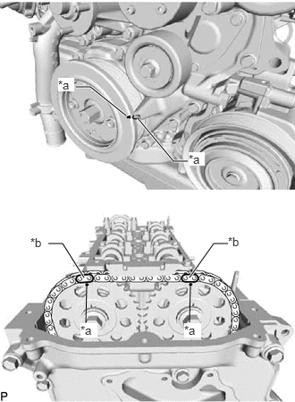
| *a | Timing Mark |
| *b | Paint Mark |
Align the timing mark of the crankshaft pulley and timing chain cover by rotating the crankshaft clockwise.
Make sure that the timing mark of the camshaft timing sprocket is at the top.
- HINT:
-
If the timing mark is not at the top, turn the crankshaft pulley 1 revolution so that the timing mark is at the top (set the No. 1 piston to TDC/compression).
Place paint marks on the No. 2 chain sub-assembly.
77.REMOVE NO. 3 CAMSHAFT BEARING CAP
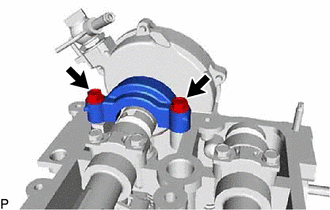
Remove the 2 bolts and No. 3 camshaft bearing cap from the cylinder head sub-assembly.
29300
78.REMOVE VACUUM PUMP ASSEMBLY
11382C
79.REMOVE CAMSHAFT OIL SEAL RETAINER
13566B
80.REMOVE TIMING CHAIN GUIDE
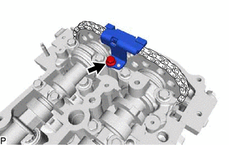
Remove the bolt and timing chain guide from the cylinder head sub-assembly.
81.REMOVE CAMSHAFT
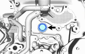
Remove the oil pump relief valve plug and gasket from the timing chain cover.
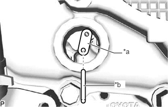
| *a | Stopper Plate |
| *b | Pin |
Insert a pin into the stopper plate hole of the No. 2 chain tensioner assembly and lock the No. 2 chain tensioner assembly.
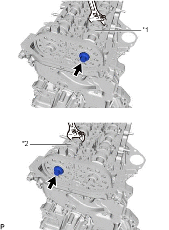
| *1 | No. 1 Camshaft |
| *2 | No. 2 Camshaft |
Hold the hexagonal portion of the camshaft with a wrench and loosen the 2 bolts from the No. 1 camshaft and No. 2 camshaft.
- NOTICE:
-
Be careful not to damage the cylinder head sub-assembly with the wrench.
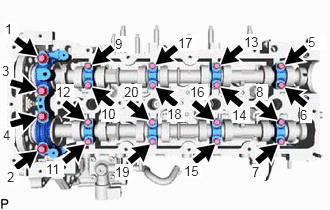
Using several steps, remove the 20 bolts, No. 1 camshaft bearing cap and 8 No. 2 camshaft bearing caps from the cylinder head sub-assembly.
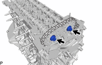
Raise the No. 1 camshaft and remove the bolt from the No. 1 camshaft.
Raise the No. 2 camshaft and remove the bolt from the No. 2 camshaft.
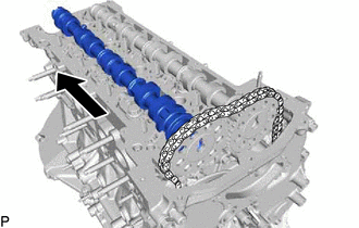
Remove the No. 2 camshaft from the camshaft timing sprocket.
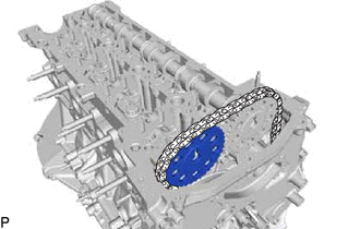
Remove the camshaft timing sprocket from the No. 2 chain sub-assembly.
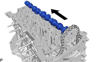
Remove the No. 1 camshaft from the camshaft timing sprocket.
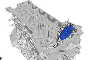
Remove the camshaft timing sprocket from the No. 2 chain sub-assembly.
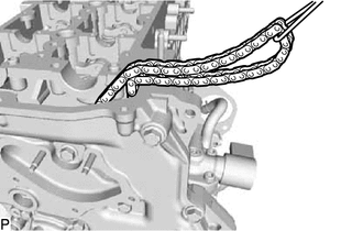
Suspend the No. 2 chain sub-assembly with a string or equivalent.
- HINT:
-
Be careful not to drop the No. 2 chain sub-assembly inside the timing chain cover assembly.