1GD-FTV LUBRICATION OIL PUMP INSTALLATION
CAUTION / NOTICE / HINT
- NOTICE:
- ·
When replacing the parts in the following chart (A), replace the No. 1 injection pipe sub-assembly, No. 2 injection pipe sub-assembly and/or fuel inlet pipe sub-assembly with new ones.
Replaced Parts (A) Pipes Requiring New Replacement Injector assembly (including shuffling the injector assemblies between the cylinders) ·No. 1 injection pipe sub-assembly
·No. 2 injection pipe sub-assembly
Supply pump assembly Fuel inlet pipe sub-assembly ·Common rail assembly
·Cylinder block sub-assembly
·Cylinder head sub-assembly
·Cylinder head gasket
·Timing chain case assembly
·No. 1 injection pipe sub-assembly
·No. 2 injection pipe sub-assembly
·Fuel inlet pipe sub-assembly
·After removing the No. 1 injection pipe sub-assembly, No. 2 injection pipe sub-assembly and/or fuel inlet pipe sub-assembly, clean them with a brush and compressed air.
·The injector assembly is a precision instrument. Do not use the injector assembly if it is struck or dropped.
·Make sure foreign matter does not enter the fuel path.
·The supply pump assembly is a precision instrument. Do not use the supply pump assembly if it is struck or dropped.
·Hold the supply pump assembly itself during removal and installation. Do not hold the pre-stroke control valve or fuel pipe, etc.
PROCEDURE

 11310
1.INSTALL TIMING CHAIN CASE ASSEMBLY AND ENGINE WATER PUMP ASSEMBLY
Install a new gasket to the timing chain case assembly.
Install the 4 new O-rings to the cylinder block sub-assembly and cylinder head sub-assembly.
Clean and degrease the contact surfaces of the timing chain case assembly, cylinder head sub-assembly and cylinder block sub-assembly.
Apply a coating of seal packing to the timing chain case assembly at the points shown in the illustration.
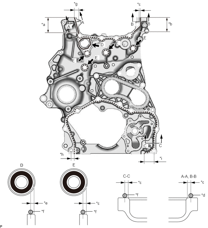
| *a | 46 mm (1.81 in.) | *b | 50 mm (1.97 in.) |
| *c | 2.0 to 3.0 mm (0.0787 to 0.118 in.) | *d | 2.5 to 3.5 mm (0.0984 to 0.138 in.) |
| *e | 3.0 to 4.0 mm (0.118 to 0.158 in.) | *f | 1.5 to 2.5 mm (0.0591 to 0.0984 in.) |
| *g | 13 to 15 mm (0.512 to 0.591 in.) | *h | 9.0 to 11 mm (0.354 to 0.433 in.) |
| *i | 31 to 33 mm (1.22 to 1.30 in.) | - | - |
- Seal packing:
- for line area D:
Toyota Genuine Seal Packing 1282B, Three Bond 1282B or equivalent.
- for line area A-A, B-B, C-C and E:
Toyota Genuine Seal Packing Black, Three Bond 1207B or equivalent.
| Line Type and Area | Seal Packing Diameter | Application Area | Seal Packing Application Length |
|---|---|---|---|
| Dashed Line | 1.5 to 2.5 mm (0.0591 to 0.0984 in.) | 2.0 to 3.0 mm (0.0787 to 0.118 in.) | - |
| A - A | 2.5 to 3.5 mm (0.0984 to 0.138 in.) | 2.0 to 3.0 mm (0.0787 to 0.118 in.) | 46 mm (1.81 in.) |
| B - B | 2.5 to 3.5 mm (0.0984 to 0.138 in.) | 2.0 to 3.0 mm (0.0787 to 0.118 in.) | 50 mm (1.97 in.) |
| D | 1.5 to 2.5 mm (0.0591 to 0.0984 in.) | 3.0 to 4.0 mm (0.118 to 0.158 in.) | - |
- NOTICE:
- ·
Using non-residue solvent, clean and remove any oil from the installation surface.
·Install the part within 3 minutes and tighten the bolts within 10 minutes after applying seal packing.
·Do not add engine oil for at least 2 hours after installation.
·Do not start the engine within 2 hours after installation.
Temporarily install the timing chain case assembly with the 15 bolts.
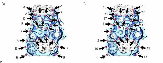
| *a | Type of bolt | *b | Tightening |
- Bolt Length:
Item Length Thread Diameter Bolt A 30 mm (1.18 in.) 8.0 mm (0.315 in.) Bolt B 45 mm (1.77 in.) 8.0 mm (0.315 in.) Bolt C 65 mm (2.56 in.) 8.0 mm (0.315 in.) Bolt D 30 mm (1.18 in.) 10 mm (0.394 in.)
Temporarily install a new gasket and the engine water pump assembly with the 8 bolts.
Tighten the 23 bolts in the order shown in the illustration.
- Torque:
- for bolt A, B and C : 29 N*m (296 kgf*cm, 21 ft.*lbf)
- for bolt D : 43 N*m (438 kgf*cm, 32 ft.*lbf)
- NOTICE:
-
Check the torque of bolt 1 after tightening bolt 23.
15605C
2.INSTALL OIL CHECK VALVE SUB-ASSEMBLY (w/ 2 Stage Hydraulic Switching Oil Pump System)
Using a 5 mm hexagon wrench, install the oil check valve sub-assembly to the timing gear case assembly with the bolt.
- Torque:
- 9.0 N*m (92 kgf*cm, 80 in.*lbf)
15350
3.INSTALL OIL PRESSURE SWITCHING VALVE ASSEMBLY (w/ 2 Stage Hydraulic Switching Oil Pump System)
22815A
4.INSTALL INJECTION PUMP INSULATOR
22100
5.INSTALL SUPPLY PUMP ASSEMBLY
13559
6.INSTALL NO. 1 CHAIN TENSIONER SLIPPER
13561
7.TEMPORARILY INSTALL NO. 1 CHAIN VIBRATION DAMPER
13506
8.INSTALL CRANKSHAFT TIMING GEAR OR SPROCKET, INJECTION PUMP DRIVE GEAR WITH NO. 1 CHAIN SUB-ASSEMBLY
13561
9.TIGHTEN NO. 1 CHAIN VIBRATION DAMPER
13540
10.INSTALL NO. 1 CHAIN TENSIONER ASSEMBLY
11.INSTALL SUPPLY PUMP SHAFT NUT
13523
12.INSTALL CAMSHAFT TIMING SPROCKET
13562
13.INSTALL NO. 2 CHAIN VIBRATION DAMPER
13507
14.INSTALL NO. 2 CHAIN SUB-ASSEMBLY
13559
15.INSTALL NO. 2 CHAIN TENSIONER SLIPPER
13550
16.INSTALL NO. 2 CHAIN TENSIONER ASSEMBLY
13566B
17.INSTALL TIMING CHAIN GUIDE
18.CHECK NO. 1 CYLINDER TO TDC/COMPRESSION
13639
19.INSTALL BALANCE SHAFT TIMING SPROCKET, BALANCE SHAFT TIMING GEAR AND NO. 3 CHAIN SUB-ASSEMBLY
11991A
20.INSTALL NO. 1 BALANCE SHAFT THRUST PLATE
13560A
21.INSTALL NO. 3 CHAIN TENSIONER ASSEMBLY
13519
22.INSTALL OIL PUMP DRIVE GEAR
Install the oil pump drive gear to the crankshaft.
11324
23.INSTALL TIMING CHAIN COVER PLATE
11302
24.INSTALL TIMING CHAIN COVER SUB-ASSEMBLY
Apply a light coat of engine oil to a new timing chain case gasket.
Install the timing chain case gasket to the timing chain case assembly.
Clean and degrease the contact surfaces of the timing chain cover sub-assembly and timing chain case assembly.
Apply a coating of seal packing to the timing chain cover sub-assembly at the points shown in the illustration.
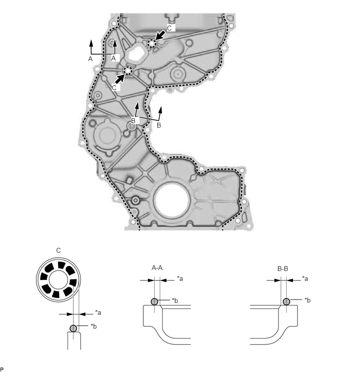
| *a | 2.0 to 3.0 mm (0.0787 to 0.118 in.) | *b | 2.5 to 3.5 mm (0.0984 to 0.138 in.) |
- Seal packing:
Toyota Genuine Seal Packing Black, Three Bond 1207B or equivalent.
- Standard seal packing diameter:
2.5 to 3.5 mm (0.0984 to 0.138 in.)
- NOTICE:
- ·
Using non-residue solvent, clean and remove any oil from the installation surface.
·Install the part within 3 minutes and tighten the bolts within 10 minutes after applying seal packing.
·Do not add engine oil for at least 2 hours after installation.
·Do not start the engine within 2 hours after installation.
Temporarily install the timing chain cover sub-assembly with the 20 bolts.
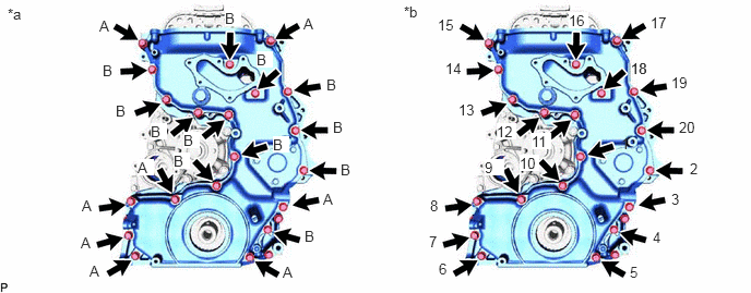
| *a | Type of bolt | *b | Tightening |
- Bolt Length:
Item Length Thread Diameter Bolt A 38 mm (1.50 in.) 8.0 mm (0.315 in.) Bolt B 25 mm (0.984 in.) 8.0 mm (0.315 in.)
Tighten the 20 bolts in the order shown in the illustration.
- Torque:
- 21 N*m (214 kgf*cm, 15 ft.*lbf)
- NOTICE:
-
Check the torque of bolt 1 after tightening bolt 20.
11303A
25.INSTALL FRONT CRANKSHAFT OIL SEAL
12101
26.INSTALL OIL PAN SUB-ASSEMBLY
Clean and degrease the contact surfaces of the oil pan sub-assembly and cylinder block sub-assembly.
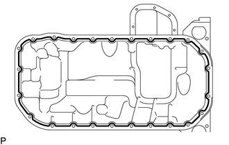
Apply seal packing in a continuous line as shown in the illustration.

|
Seal Packing |
- Seal packing:
Toyota Genuine Seal Packing Black, Three Bond 1207B or equivalent
- Standard seal diameter:
3.5 to 4.5 mm (0.138 to 0.177 in.)
- NOTICE:
- ·
Remove any oil from the contact surface.
·Install the oil pan sub-assembly within 3 minutes and tighten the bolts and nuts within 10 minutes after applying seal packing.
·Do not add engine oil within 2 hours after installation.
·Do not start the engine for at least 2 hours after installation.
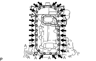
Install the oil pan sub-assembly to the cylinder block sub-assembly with the 23 bolts and 2 nuts.
- Torque:
- 10 N*m (102 kgf*cm, 7 ft.*lbf)
- NOTICE:
-
Check the torque of all nuts and bolts labeled A again.
89491
27.INSTALL ENGINE OIL LEVEL SENSOR
12102A
28.INSTALL NO. 2 OIL PAN SUB-ASSEMBLY
Clean and degrease the contact surfaces of the No. 2 oil pan sub-assembly and cylinder block sub-assembly.
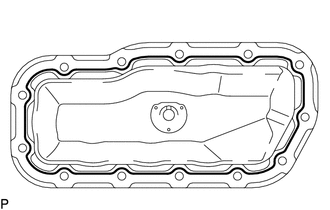
Apply seal packing in a continuous line as shown in the illustration.
|
|
Seal Packing |
- Seal packing:
Toyota Genuine Seal Packing Black, Three Bond 1207B or equivalent
- Standard seal diameter:
3.5 to 4.5 mm (0.138 to 0.177 in.)
- NOTICE:
- ·
Remove any oil from the contact surface.
·Install the No. 2 oil pan sub-assembly within 3 minutes and tighten the bolts and nuts within 10 minutes after applying seal packing.
·Do not add engine oil within 2 hours after installation.
·Do not start the engine for at least 2 hours after installation.
Install the No. 2 oil pan sub-assembly to the oil pan sub-assembly with the 11 bolts and 2 nuts.
- Torque:
- 10 N*m (102 kgf*cm, 7 ft.*lbf)
11201
29.INSTALL CYLINDER HEAD COVER SUB-ASSEMBLY
Apply a light coat of engine oil to the O-ring of the camshaft position sensor.
Install a new cylinder head cover gasket, No. 2 cylinder head cover gasket and 2 camshaft bearing cap oil hole gaskets to the cylinder head cover sub-assembly.
Clean and degrease the contact surfaces of the cylinder head cover sub-assembly and cylinder head sub-assembly.
Apply seal packing as shown in the illustration.
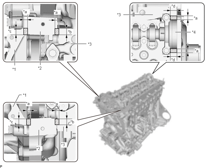
| *1 | Timing Chain Cover Sub-assembly | *2 | Timing Chain Case Assembly |
| *3 | Cylinder Head Sub-assembly | *4 | No. 3 Camshaft Bearing Cap |
| *a | Seal Diameter: 3.0 to 6.0 mm (0.118 to 0.236 in.) | *b | Application Width: 7.0 mm (0.276 in.) |
| *c | Application Width: 9.0 mm (0.354 in.) | *d | Application Width: 11.0 mm (0.433 in.) |
- Seal packing:
Toyota Genuine Seal Packing Black, Three Bond 1207B or equivalent
- Standard seal diameter:
3.0 to 6.0 mm (0.118 to 0.236 in.)
- NOTICE:
- ·
Remove any oil from the contact surface.
·Install the cylinder head cover sub-assembly within 3 minutes and tighten the bolts within 10 minutes after applying seal packing.
·Do not add engine oil for at least 2 hours after installation.
·Do not start the engine within 2 hours after installation.
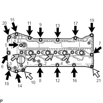
|
|
Bolt |

|
Nut |

|
Nozzle Holder Clamp Seat |
Tighten the 14 bolts, 4 nozzle holder clamp seats, 2 nuts and camshaft position sensor in the order shown in the illustration.
- Torque:
- 10 N*m (107 kgf*cm, 7 ft.*lbf)
- NOTICE:
- ·
When reusing the camshaft position sensor, check the O-rings.
·Make sure that the O-ring is not cracked or jammed when installing it on the cylinder head cover sub-assembly.
·Replace with a new part if it is dropped or if it receives a strong impact.
·Check the torque of bolts 1 to 4 again.
23682
30.INSTALL NOZZLE HOLDER GASKET
23670
31.TEMPORARILY INSTALL INJECTOR ASSEMBLY
12501
32.INSTALL GENERATOR BRACKET SUB-ASSEMBLY
12281A
33.INSTALL NO. 1 ENGINE HANGER
16575C
34.INSTALL NO. 1 WATER HOSE CLAMP BRACKET (w/ DPF)
13471
35.INSTALL CRANKSHAFT PULLEY
13496
36.INSTALL CRANKSHAFT PULLEY COVER
88451B
37.INSTALL VISCOUS HEATER CRANKSHAFT PULLEY (w/ Viscous Heater)
16620
38.INSTALL V-RIBBED BELT TENSIONER ASSEMBLY
Install the V-ribbed belt tensioner assembly to the timing chain cover sub-assembly with 3 bolts.
- Torque:
- 21 N*m (214 kgf*cm, 15 ft.*lbf)
16603
39.INSTALL NO. 1 IDLER PULLEY SUB-ASSEMBLY
Install the No. 1 idler pulley sub-assembly to the generator bracket sub-assembly with the bolt.
- Torque:
- 43 N*m (438 kgf*cm, 32 ft.*lbf)
16331A
40.INSTALL THERMOSTAT
16321
41.INSTALL WATER INLET
16304
42.INSTALL WATER OUTLET SUB-ASSEMBLY
16207
43.INSTALL NO. 2 WATER BY-PASS PIPE SUB-ASSEMBLY
15407
44.TEMPORARILY INSTALL TURBO OIL INLET PIPE SUB-ASSEMBLY
17141
45.TEMPORARILY INSTALL EXHAUST MANIFOLD WITH TURBOCHARGER SUB-ASSEMBLY
15474
46.INSTALL TURBO OIL OUTLET PIPE
17293
47.TEMPORARILY INSTALL TURBOCHARGER STAY
17141
48.TIGHTEN EXHAUST MANIFOLD WITH TURBOCHARGER SUB-ASSEMBLY
17293
49.TIGHTEN TURBOCHARGER STAY
87101
50.INSTALL NO. 1 VISCOUS HEATER BRACKET SUB-ASSEMBLY (w/ Viscous Heater)
16284
51.CONNECT NO. 1 AND NO.2 TURBO WATER HOSE
16268
52.INSTALL NO. 1 WATER BY-PASS PIPE
16279
53.INSTALL NO. 3 WATER BY-PASS PIPE
89463C
54.INSTALL NO. 1 NITROGEN OXIDES SENSOR (w/ Urea SCR System)
17291
55.INSTALL TURBINE OUTLET ELBOW (w/o EGR Cooler)
25051
56.INSTALL EXHAUST MANIFOLD CONVERTER SUB-ASSEMBLY (w/ EGR Cooler)
57.INSTALL NO. 2 EXHAUST PIPE SUPPORT STAY (w/o DPF)
w/ EGR Cooler:
Click hereEngine / Hybrid System>1GD-FTV (EMISSION CONTROL)>MONOLITHIC CONVERTER (w/o DPF)>INSTALLATION
w/o EGR Cooler:
Click hereEngine / Hybrid System>1GD-FTV (ENGINE MECHANICAL)>ENGINE UNIT>INSTALLATION
17118
58.INSTALL NO. 2 EXHAUST PIPE SUPPORT STAY (w/ DPF)
89463C
59.CONNECT NO. 1 NITROGEN OXIDES SENSOR (w/ Urea SCR System)
17271
60.INSTALL NO. 1 TURBO INSULATOR (w/o DPF)
w/ EGR Cooler:
Click hereEngine / Hybrid System>1GD-FTV (EMISSION CONTROL)>MONOLITHIC CONVERTER (w/o DPF)>INSTALLATION
w/o EGR Cooler:
Click hereEngine / Hybrid System>1GD-FTV (ENGINE MECHANICAL)>ENGINE UNIT>INSTALLATION
17271
61.INSTALL NO. 1 TURBO INSULATOR (w/ DPF)
17167
62.INSTALL NO. 1 EXHAUST MANIFOLD HEAT INSULATOR (w/o DPF)
w/ EGR Cooler:
Click hereEngine / Hybrid System>1GD-FTV (EMISSION CONTROL)>MONOLITHIC CONVERTER (w/o DPF)>INSTALLATION
w/o EGR Cooler:
Click hereEngine / Hybrid System>1GD-FTV (ENGINE MECHANICAL)>ENGINE UNIT>INSTALLATION
17167
63.INSTALL NO. 1 EXHAUST MANIFOLD HEAT INSULATOR (w/ DPF)
89467B
64.INSTALL AIR FUEL RATIO SENSOR (w/ DPF)
17168
65.INSTALL NO. 2 EXHAUST MANIFOLD HEAT INSULATOR (w/ DPF)
23295D
66.INSTALL NO. 1 INJECTOR HOLDER (w/ DPF)
16281
67.CONNECT NO. 4 WATER BY-PASS HOSE (w/ DPF)
16282
68.INSTALL NO. 5 WATER BY-PASS HOSE (w/ DPF)
69.INSTALL WATER BY-PASS HOSE (w/ Urea SCR System)
12229
70.INSTALL PCV PIPE (for Cold Area Specification Vehicles)
12261
71.INSTALL PCV HOSE (except Cold Area Specification Vehicles)
88431
72.INSTALL NO. 1 COMPRESSOR MOUNTING BRACKET
23815D
73.INSTALL NO. 3 FUEL PIPE
74.INSTALL HOSE BRACKET
23701
75.INSTALL NO. 1 AND NO. 2 INJECTION PIPE SUB-ASSEMBLY
23670
76.TIGHTEN INJECTOR ASSEMBLY
23701
77.TIGHTEN NO. 1 AND NO. 2 INJECTION PIPE SUB-ASSEMBLY
82715
78.INSTALL WIRING HARNESS CLAMP BRACKET
23760
79.INSTALL NOZZLE LEAKAGE PIPE ASSEMBLY
23811H
80.INSTALL NO. 1 FUEL PIPE (w/ DPF)
81.INSTALL WIRING HARNESS CLAMP BRACKET
17111
82.INSTALL INTAKE MANIFOLD
23770
83.INSTALL NO. 2 NOZZLE LEAKAGE PIPE ASSEMBLY
23804C
84.INSTALL FUEL INLET PIPE SUB-ASSEMBLY
23815D
85.INSTALL NO. 3 FUEL PIPE
23804D
86.INSTALL NO. 4 FUEL PIPE (w/o DPF)
23804D
87.INSTALL NO. 4 FUEL PIPE SUB-ASSEMBLY (w/ DPF)
23271H
88.INSTALL NO. 1 FUEL HOSE
23273H
89.INSTALL NO. 2 FUEL HOSE
23243B
90.INSTALL FUEL PUMP MOTOR WIRE
22803
91.INSTALL FUEL INJECTION PUMP COVER SUB-ASSEMBLY
17118
92.INSTALL MANIFOLD STAY
82715
93.INSTALL WIRING HARNESS CLAMP BRACKET
23812D
94.INSTALL NO. 2 FUEL PIPE
11409
95.INSTALL ENGINE OIL LEVEL DIPSTICK GUIDE
25624
96.INSTALL EGR VALVE ADAPTER (w/o EGR System)
97.INSTALL EGR VALVE ADAPTER SUB-ASSEMBLY WITH ELECTRIC EGR CONTROL VALVE ASSEMBLY (w/ EGR System without EGR Cooler)
25800
98.INSTALL NO. 1 EGR COOLER AND NO. 2 EGR VALVE ASSEMBLY WITH ELECTRIC EGR CONTROL VALVE ASSEMBLY (w/ EGR System with EGR Cooler)
16209
99.INSTALL NO. 4 WATER BY-PASS PIPE SUB-ASSEMBLY
25804
100.INSTALL VACUUM CONTROL VALVE SET (w/ EGR Cooler)
25601
101.INSTALL NO. 1 EGR PIPE SUB-ASSEMBLY
16206B
102.INSTALL NO. 3 WATER BY-PASS PIPE SUB-ASSEMBLY (w/o EGR Cooler)
16206B
103.INSTALL NO. 3 WATER BY-PASS PIPE SUB-ASSEMBLY (w/ EGR Cooler)
25612
104.INSTALL NO. 2 EGR PIPE (w/ EGR System)
25625
105.INSTALL EGR VALVE BRACKET (w/ EGR System)
89421C
106.INSTALL DIESEL TURBO PRESSURE SENSOR
23265C
107.INSTALL GAS FILTER
12631A
108.INSTALL ENGINE COVER BRACKET
17578B
109.INSTALL PIPE CLAMP (w/ DPF)
25734
110.TEMPORARILY INSTALL NO. 2 VACUUM PIPE (w/ DPF)
25733A
111.TEMPORARILY INSTALL NO. 1 VACUUM PIPE (w/ DPF)
25734
112.TIGHTEN NO. 2 VACUUM PIPE (w/ DPF)
25733A
113.TIGHTEN NO. 1 VACUUM PIPE (w/ DPF)
89425
114.INSTALL EXHAUST GAS TEMPERATURE SENSOR (w/ DPF)
89481B
115.INSTALL DIFFERENTIAL PRESSURE SENSOR (w/ DPF)
16278
116.INSTALL NO. 2 WATER BY-PASS PIPE
26100G
117.INSTALL DIESEL THROTTLE BODY ASSEMBLY
77246C
118.INSTALL FUEL MAIN TUBE SUPPORT
119.INSTALL ENGINE WIRE
12632
120.INSTALL NO. 2 ENGINE COVER BRACKET (w/o Urea SCR System)
12633
121.INSTALL NO. 3 ENGINE COVER BRACKET (w/o Urea SCR System)
122.INSTALL ENGINE ASSEMBLY