HEATING / AIR CONDITIONING AIR CONDITIONING UNIT(for LHD) REMOVAL
CAUTION / NOTICE / HINT
- CAUTION:
- ·
Working on 12 V vehicle electrical system.
Risk of short circuits. Risk of fire.
-Detach battery earth lead from battery.
·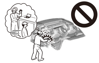
Airbag unit.
Danger. Life-threatening injuries.
-All work on pyrotechnic parts may be carried out by technically experienced and appropriately trained personnel only.
-Replace any damaged part or ones that have been dropped.
-For additional information see: Safety regulations on handling components with gas generators.
Click hereVehicle Interior>SUPPLEMENTAL RESTRAINT SYSTEMS>AIRBAG SYSTEM>PRECAUTION
- NOTICE:
- ·
Electrostatic discharge.
Damage to or destruction of electrical components.
-Leave electrical components in original packaging until just before they are installed. Use the original packaging only for any return shipments. Always package removed components straight away.
-Only touch the housings of electrical components. Do not touch pins or multi-pin connectors directly.
-Antistatic work clothing and antistatic shoes (with ESD symbol).
-For additional information see:
Click hereGeneral>INTRODUCTION>REPAIR INSTRUCTION>PRECAUTION
·Scratches.
Tools and sharp-edged components can cause scratches.
-Protect working area.
-Handle tools and components carefully.
PROCEDURE

 1. RECOVER REFRIGERANT FROM REFRIGERATION SYSTEM
2.DRAIN ENGINE COOLANT (for B48)
3.DRAIN ENGINE COOLANT (for B58)
53681
4.REMOVE UPPER CENTER FRONT SUSPENSION BRACE
5.REMOVE ECM (for B48)
6.REMOVE ECM (for B58)
7.REMOVE NO. 1 INTEGRATION RELAY
8.REMOVE ENGINE ROOM ECM BOX
for B48:
Click hereEngine / Hybrid System>B48 (ENGINE MECHANICAL)>ENGINE ASSEMBLY>REMOVAL
for B58:
Click hereEngine / Hybrid System>B58 (ENGINE MECHANICAL)>ENGINE ASSEMBLY>REMOVAL
16470
9.REMOVE RADIATOR RESERVE TANK ASSEMBLY
88710
10.SEPARATE AIR CONDITIONER TUBE ASSEMBLY
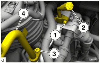
Remove T30 bolt (1) and remove air conditioner tube assembly (2).
Remove T45 bolt (3) and remove the suction pipe sub-assembly (4).
Remove the O-rings.
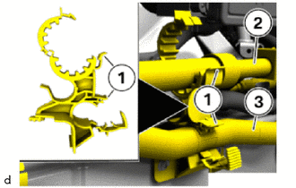
Unlock the holder with the catches (1) and open.
Remove the air conditioner tube assembly (2) and the heater water hose (3) from the holder.
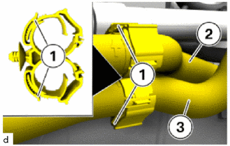
Unlock the holder with the catches (1) and open.
Remove the heater water hose (2) and (3) from the holder.
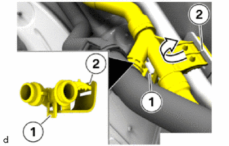
Remove catch (1).
Feed the heater water hose in the direction of the arrow from the receptacle on the air conditioner tube assembly (2).
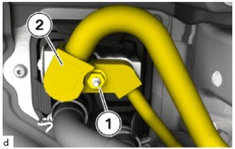
Remove nut (1).
Disconnect the air conditioner tube assembly (2) from the cooler expansion valve.
Remove the O-ring.
55606
11.REMOVE NO. 1 INSTRUMENT PANEL UNDER COVER SUB-ASSEMBLY
55607
12.REMOVE NO. 2 INSTRUMENT PANEL UNDER COVER SUB-ASSEMBLY
73990
13.REMOVE LOWER NO. 2 INSTRUMENT PANEL AIRBAG ASSEMBLY
73900
14.REMOVE LOWER NO. 1 INSTRUMENT PANEL AIRBAG ASSEMBLY (w/ Passenger Side Knee Airbag)
87211
15.REMOVE NO. 1 AIR DUCT
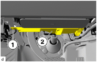
Remove screw (1).
Remove No. 1 air duct (2).
87211A
16.REMOVE NO. 2 AIR DUCT
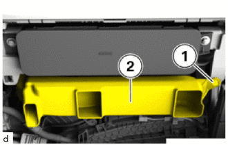
Remove screw (1).
Remove No. 2 air duct (2).
87050C
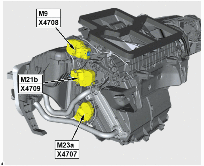
17.REMOVE NO. 1 AIR CONDITIONING RADIATOR DAMPER SERVO SUB-ASSEMBLY (M23a)
- HINT:
-
Overview of No. 1 air conditioning radiator damper servo sub-assembly of air conditioning unit assembly:
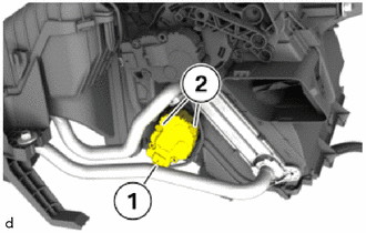
Disconnect the connector (1).
Remove T20 screws (2).
Remove No. 1 air conditioning radiator damper servo sub-assembly (M23a).
87050C
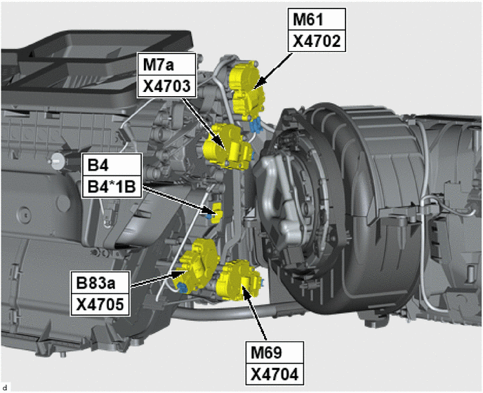
18.REMOVE NO. 1 AIR CONDITIONING RADIATOR DAMPER SERVO SUB-ASSEMBLY (M83a)
- HINT:
-
Overview of No. 1 air conditioning radiator damper servo sub-assembly of air conditioning unit assembly:
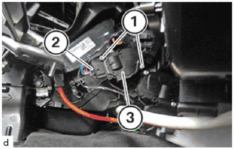
Disconnect the connector (2).
Remove T20 screws (1).
Remove No. 1 air conditioning radiator damper servo sub-assembly (M83a) (3).
87103B
19.REMOVE BLOWER WITH FAN MOTOR SUB-ASSEMBLY
87050C
20.REMOVE NO. 1 AIR CONDITIONING RADIATOR DAMPER SERVO SUB-ASSEMBLY (M61)
- HINT:
-
Overview of No. 1 air conditioning radiator damper servo sub-assembly of air conditioning unit assembly:
-
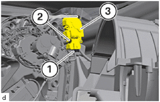
Disconnect the connector (1).
Remove T20 screws (2).
Remove No. 1 air conditioning radiator damper servo sub-assembly (M61) (3).
87050C
21.REMOVE NO. 1 AIR CONDITIONING RADIATOR DAMPER SERVO SUB-ASSEMBLY (M7a)
- HINT:
-
Overview of No. 1 air conditioning radiator damper servo sub-assembly of air conditioning unit assembly:
-
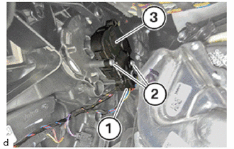
Disconnect the connector (1).
Remove T20 screws (2).
Remove No. 1 air conditioning radiator damper servo sub-assembly (M7a) (3).
87050C
22.REMOVE NO. 1 AIR CONDITIONING RADIATOR DAMPER SERVO SUB-ASSEMBLY (M69)
- HINT:
-
Overview of No. 1 air conditioning radiator damper servo sub-assembly of air conditioning unit assembly:
-
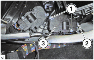
Disconnect the connector (2).
Remove T20 screws (1).
Remove No. 1 air conditioning radiator damper servo sub-assembly (M69) (3).
55011A
23.REMOVE NO. 1 INSTRUMENT PANEL GARNISH SUB-ASSEMBLY
55550
24.REMOVE GLOVE COMPARTMENT DOOR ASSEMBLY
87050C
25.REMOVE NO. 1 AIR CONDITIONING RADIATOR DAMPER SERVO SUB-ASSEMBLY (M16)
- HINT:
-
Overview of No. 1 air conditioning radiator damper servo sub-assembly of air conditioning unit assembly:
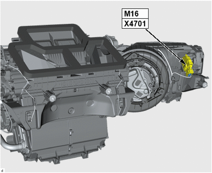
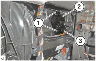
Disconnect the connector (3).
Remove T20 screws (1).
Remove No. 1 air conditioning radiator damper servo sub-assembly (M16) (2).
26.REMOVE INSTRUMENT PANEL SAFETY PAD ASSEMBLY
87050C
27.REMOVE NO. 1 AIR CONDITIONING RADIATOR DAMPER SERVO SUB-ASSEMBLY (M21b)
- HINT:
-
Overview of No. 1 air conditioning radiator damper servo sub-assembly of air conditioning unit assembly:
-
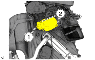
Disconnect the connector (1).
Remove T20 screws (2).
Remove No. 1 air conditioning radiator damper servo sub-assembly (M21b).
28.REMOVE RADIO RECEIVER ASSEMBLY (w/o Navigation System)
29.REMOVE RADIO RECEIVER ASSEMBLY (w/ Navigation System)
55468C
30.REMOVE NO. 1 INSTRUMENT CLUSTER FINISH PANEL SEAL
83108
31.REMOVE METER MIRROR SUB-ASSEMBLY
45250
32.SEPARATE STEERING COLUMN ASSEMBLY
55305C
33.REMOVE INSTRUMENT PANEL REINFORCEMENT SUB-ASSEMBLY
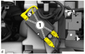
Disconnect the connectors (1).
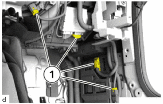
Disconnect the connectors (1).
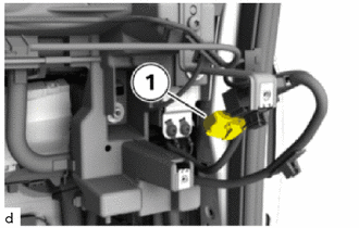
Disconnect the connector (1).
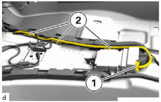
Disconnect the connector (1).
Disengage the clamps (2) and move the cable harness aside.
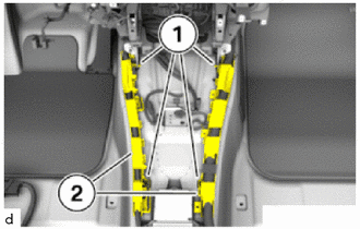
Disengage the claws (1) and put the cable ducts (2) aside.
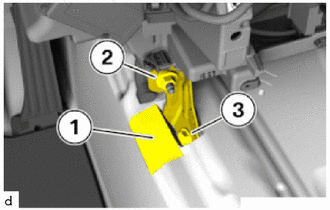
Fold the carpet (1) to the side in the marked area.
Remove the No. 1 instrument panel bracket with the nut (2) and bolt (3).
- HINT:
- ·
The right-hand side component is shown. The procedure on the right is identical.
·Carry out the work steps on the left and right side.
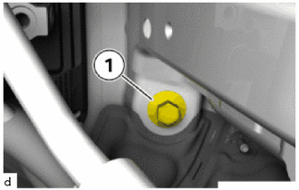
Using a socket wrench 16 mm, remove the bolt (1) in the engine compartment.
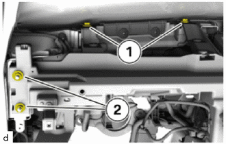
Loosen bolts (1) a few turns.
- NOTICE:
-
Do not remove the bolts (1).
Remove nuts (2).
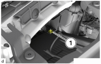
Remove nut (1).
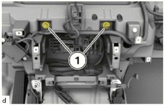
Remove nuts (1).
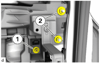
Remove nuts (1) and (2).
Carefully feed out the instrument panel reinforcement sub-assembly with the wiring harness to the rear.
- NOTICE:
-
Conduct the following operation with the assistance of a second person.
Carefully remove the instrument panel reinforcement sub-assembly including vehicle wiring harness from the vehicle interior.
- NOTICE:
-
Conduct the following operation with the assistance of a second person.
88515
34.REMOVE COOLER EXPANSION VALVE
87010
35.REMOVE AIR CONDITIONING UNIT ASSEMBLY
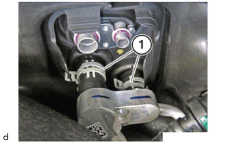
Slide the hose clamps (1) to disconnect the heater water hoses.
- NOTICE:
-
Prepare a drain pan or cloth in case the coolant leaks.
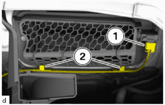
Disconnect the connector (1).
Disengage the clamps (2) and put the cable harness aside.
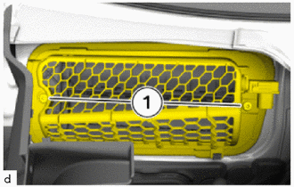
Remove T25 screws (1) and remove No. 1 air duct sub-assembly.
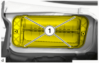
Disengage the claws (1) on the air conditioning unit assembly.
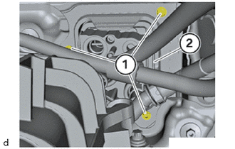
Remove T25 screws (1) from air conditioning unit assembly (2).
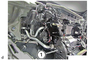
Remove air conditioning unit assembly (1).
- NOTICE:
-
Protect carpet in footwell against escaping coolant.