B48 ENGINE MECHANICAL ENGINE ASSEMBLY INSTALLATION
PROCEDURE

 1.INSTALL SPACER BRACKET
Install the 2 spacer brackets (1).
- Torque:
- 12 N*m (122 kgf*cm, 9 ft.*lbf)
2.REMOVE ENGINE STAND
- HINT:
-
Conduct the following operation with the assistance of a second person.
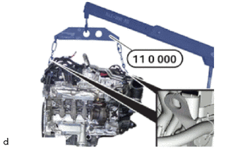
Connect both hooks of the special tool 0 490 561 (11 0 000) to the front and back of the engine with the engine hangers.
- SST
- 09200-WA870
- HINT:
-
The workshop crane, lifting gear and the engine hangers on the engine must all be connected to each other so that the engine hangs straight upon lifting.
Raise the engine slowly.
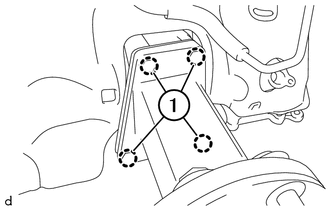
Release the bolts (1) and remove the engine stand attachment No. 1.
12311
3.INSTALL NO. 1 FRONT ENGINE MOUNTING BRACKET RH
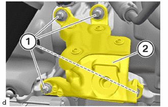
Install the No. 1 front engine mounting bracket RH (2).
Tighten the E12 bolts (1).
- Torque:
- 38 N*m (387 kgf*cm, 28 ft.*lbf)
4.INSTALL ENGINE ASSEMBLY
- CAUTION:
- ·
Components connected to the engine joint or cross member.
Danger of injury!
-Check lifting eyes and engine mounting brackets for damage, e.g. cracks.
-Attach the component to correctly mounted engine joints or cross members only.
-Exclusively lift the component, do not move it forwards, backwards or in transverse direction.
Install and lower the engine.
Make sure that the No. 1 front engine mounting brackets rest completely on the front engine mounting insulators.
12315
5.INSTALL NO. 1 FRONT ENGINE MOUNTING BRACKET LH
- NOTICE:
-
In order to prevent play, lower the engine completely before screwing the engine mount and engine mounting bracket.
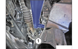
Tighten down E14 bolt (1).
- Torque:
- 100 N*m (1020 kgf*cm, 74 ft.*lbf)
12311
6.INSTALL NO. 1 FRONT ENGINE MOUNTING BRACKET RH
- NOTICE:
-
In order to prevent play, lower the engine completely before screwing the engine mount and engine mounting bracket.
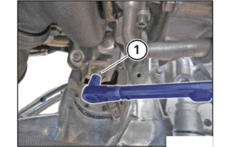
Tighten down E14 bolt (1).
- Torque:
- 100 N*m (1020 kgf*cm, 74 ft.*lbf)
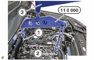
Release both hooks (1) and (2) of the special tool 0 490 561 (11 0 000) at the front and back of the engine from the engine hangers.
- SST
- 09200-WA870
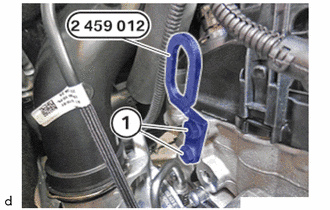
Unscrew the bolts (1) of the special tool 2 459 012.
- SST
- 09200-WA610
Feed out the special tool 2 459 012 at the cylinder head and remove.
- SST
- 09200-WA610
88707
7.INSTALL SUCTION PIPE SUB-ASSEMBLY
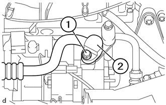
Replace O-ring.
Position suction pipe sub-assembly (2).
Tighten the T45 bolts (1).
- Torque:
- 19 N*m (194 kgf*cm, 14 ft.*lbf)
88710
8.INSTALL AIR CONDITIONING TUBE ASSEMBLY
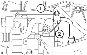
Replace O-ring.
Position air conditioning tube assembly (2).
Tighten the T45 bolts (1).
- Torque:
- 19 N*m (194 kgf*cm, 14 ft.*lbf)
9.INSTALL OIL COOLER TUBE
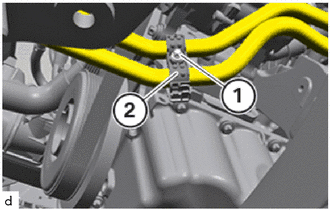
Position the oil cooler tube in the No. 1 automatic transmission oil cooler tube clamp (2).
Tighten down T25 screw (1).
- Torque:
- 5.0 N*m (51 kgf*cm, 44 in.*lbf)
35000
10.TEMPORARILY TIGHTEN AUTOMATIC TRANSMISSION ASSEMBLY
35000
11.FULLY TIGHTEN AUTOMATIC TRANSMISSION ASSEMBLY
17119
12.INSTALL NO. 2 MANIFOLD STAY
13.INSTALL PROPELLER SHAFT ASSEMBLY
57255
14.INSTALL REAR ENGINE MOUNTING MEMBER
58151
15.INSTALL FLOOR HEAT INSULATOR
58151
16.INSTALL FRONT NO. 1 FLOOR HEAT INSULATOR
58166A
17.INSTALL FRONT FLOOR COVER LH
58165C
18.INSTALL FRONT FLOOR COVER RH
- HINT:
-
Use the same procedure as for the LH side.
25051
19.INSTALL EXHAUST MANIFOLD CONVERTER SUB-ASSEMBLY
28100
20.INSTALL STARTER ASSEMBLY
21.CONNECT WATER HOSE
- HINT:
-
Make sure that the connections are locked correctly. The locks must engage audibly.
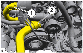
Connect and lock the No. 1 radiator hose (1) and (2).
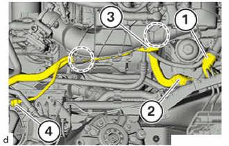
Connect and lock the radiator reserve tank hose (4).
Connect and lock the No. 5 water by-pass hose (3) in the marked area.
Clip in the No. 5 water by-pass hose (3) in the marked area.
Connect and lock the heater water hose (1) and No. 1 water by-pass hose (2).
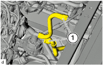
Connect and lock the No. 7 water by-pass hose and No. 6 radiator hose (1).
16572D
22.INSTALL NO. 2 RADIATOR HOSE
11401T
23.INSTALL CYLINDER BLOCK COVER
17882
24.INSTALL NO. 2 AIR CLEANER HOSE
23802B
25.INSTALL NO. 2 FUEL PIPE SUB-ASSEMBLY
26.INSTALL IGNITION COIL ASSEMBLY
17880
27.INSTALL AIR CLEANER HOSE ASSEMBLY
17700
28.INSTALL AIR CLEANER ASSEMBLY
53205
29.INSTALL UPPER RADIATOR SUPPORT SUB-ASSEMBLY
53826A
30.INSTALL FRONT UPPER FENDER PROTECTOR LH
53825A
31.INSTALL FRONT UPPER FENDER PROTECTOR RH
- HINT:
-
Use the same procedure described for the LH side.
23827A
32.CONNECT NO. 2 FUEL VAPOR FEED HOSE
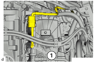
Connect and lock the No. 2 fuel vapor feed hose (1).
Engage the clamp.
33.CONNECT CONNECTOR TO BRAKE BOOSTER TUBE
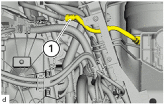
Connect and lock the connector to brake booster tube (1).
82161
34.INSTALL FLOOR WIRE
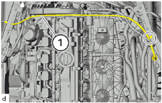
Clip in the floor wire (1) for the voltage supply of the power distribution box in the marked area.
35.INSTALL ENGINE ROOM ECM BOX
- NOTICE:
- ·
Improper routing of cables and wiring harnesses.
Trapped, crushed or damaged cables may cause short circuits and malfunctions.
-Route all cables without abrasions, do not trap and crush.
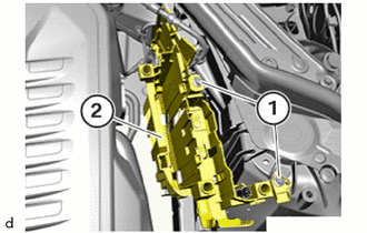
Feed the engine room ECM box (2) into the guide and install.
Tighten down bolts (1).
- Torque:
- 8.0 N*m (82 kgf*cm, 71 in.*lbf)
Feed the wiring harnesses into the holder at the engine room ECM box.
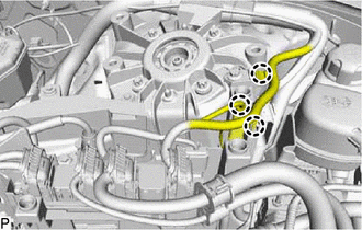
Engage the 3 clamps (marks).
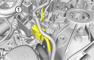
Install the connectors (1).
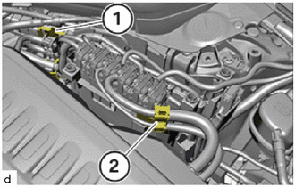
The locks (1) and (2) must engage audibly.
36.INSTALL NO. 1 INTEGRATION RELAY
37.INSTALL WIRE HARNESS CLAMP BRACKET
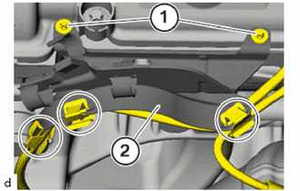
Install wire harness clamp bracket (2) for the generator wire.
Tighten the E8 screws (1).
- Torque:
- 6.0 N*m (61 kgf*cm, 53 in.*lbf)
Clip in the lines in the marked areas.
38.INSTALL POSITIVE BATTERY CABLE
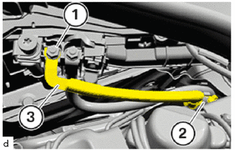
Position the starter wire (3).
Secure clamps (2).
Tighten nut (1).
- Torque:
- 19 N*m (194 kgf*cm, 14 ft.*lbf)
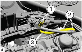
Insert and install the generator wire (3).
Secure clamps (2).
Tighten nut (1).
- Torque:
- 19 N*m (194 kgf*cm, 14 ft.*lbf)
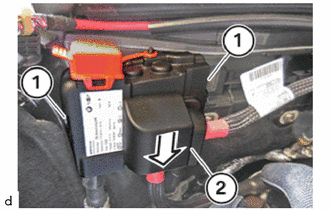
Insert and install the cover (2) in the direction of the arrow.
The locks (1) must engage audibly.
11271A
39.INSTALL REAR CYLINDER BLOCK COVER
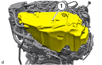
Make sure the rear cylinder block cover (1) is correctly fitted on rear side of the engine.
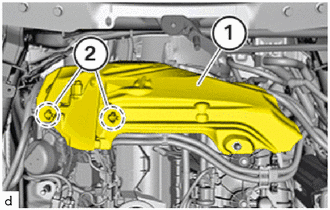
Install the rear cylinder block cover (1) from the top and clip it in at the grommets (2).
12601B
40.INSTALL NO. 1 ENGINE COVER SUB-ASSEMBLY
- NOTICE:
- ·
Damage to the No. 1 engine cover sub-assembly.
Jerky movements during disassembly and excessive application of force during installation may result in breakage of the No. 1 engine cover sub-assembly.
-Disassemble or mount the No. 1 engine cover sub-assembly carefully.
-Disassemble or mount snap-lock couplings of the ball pivots one after the other.
-Disassemble or mount No. 1 engine cover sub-assembly only at temperatures >20 °C.
Vehicle information / Control unit list / DME / Call up control unit functions / Diagnostic request / Diagnostic request / 117 Ambient temperature
-Use only distilled water as an auxiliary material during installation, no lubricants.
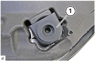
Check all grommets (1) of the No. 1 engine cover sub-assembly for correct fit.
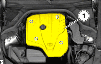
Clip in the No. 1 engine cover sub-assembly (1) into the holders in the indicated areas.
The No. 1 engine cover sub-assembly (1) must audibly engage into place.
55789B
41.INSTALL NO. 2 COWL TOP VENTILATOR LOUVER PROTECTOR
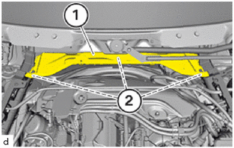
Position the No. 2 cowl top ventilator louver protector (1).
Tighten down bolts and nut (2).
- Torque:
- 2.6 N*m (27 kgf*cm, 23 in.*lbf)
55788A
42.INSTALL COWL TOP VENTILATOR LOUVER PROTECTOR
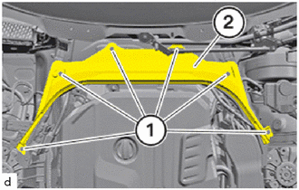
Position the cowl top ventilator louver protector (2).
Tighten the screws (1).
- Torque:
- 2.6 N*m (27 kgf*cm, 23 in.*lbf)
53681
43.INSTALL UPPER FRONT SUSPENSION CENTER BRACE
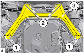
Position upper front suspension center brace (3).
Replace E14 bolts (1) and bolts (2).
Tighten the E14 bolts (1).
- Torque:
- 56 N*m (571 kgf*cm, 41 ft.*lbf)
Using SST, tighten the E14 bolts (1) an additional 90°.
- SST
- 09900-WA010
- HINT:
-
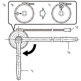 2.99,1.271 3.156,1.188 false 2.906,2.094 2.906,1.76 false 0.875,3 1.208,3 false 0.104,0.125 0.417,0.281 0.313,0.156 10 false *a 0.448,0.125 0.76,0.281 0.313,0.156 10 false *b 2.042,0.125 2.354,0.281 0.313,0.156 10 false *c 3.188,1.073 3.427,1.271 0.24,0.198 10 false *d 2.854,2.146 3.167,2.302 0.313,0.156 10 false *b 1.302,2.927 1.615,3.083 0.313,0.156 10 false *c
*a Example *b Before Tightening *c After Tightening *d Magnetic Portion
- ·
The magnetic portion is used to secure the gauge to the vehicle.
·After first adjusting the needle of the gauge to 0°, tighten to the specified angle.
·Perform the work procedure carefully so that the gauge, etc. does not become tilted.
Tighten the bolts (2).
- Torque:
- 56 N*m (571 kgf*cm, 41 ft.*lbf)
Using SST, tighten the bolts (2) an additional 90°.
- SST
- 09900-WA010
- HINT:
-
2.99,1.271 3.156,1.188 false 2.906,2.094 2.906,1.76 false 0.875,3 1.208,3 false 0.104,0.125 0.417,0.281 0.313,0.156 10 false *a 0.448,0.125 0.76,0.281 0.313,0.156 10 false *b 2.042,0.125 2.354,0.281 0.313,0.156 10 false *c 3.188,1.073 3.427,1.271 0.24,0.198 10 false *d 2.854,2.146 3.167,2.302 0.313,0.156 10 false *b 1.302,2.927 1.615,3.083 0.313,0.156 10 false *c
*a Example *b Before Tightening *c After Tightening *d Magnetic Portion
- ·
The magnetic portion is used to secure the gauge to the vehicle.
·After first adjusting the needle of the gauge to 0°, tighten to the specified angle.
·Perform the work procedure carefully so that the gauge, etc. does not become tilted.
53383
44.INSTALL HOOD TO COWL TOP SEAL
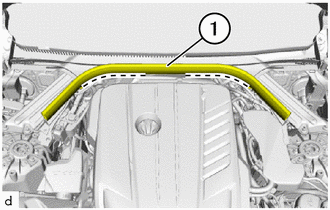
Press the hood to cowl top seal (1) into the guide.
Feed the floor cable into the brackets in the marked area.
Make sure that the hood to cowl top seal (1) and the floor cable are fitted correctly.
85010
45.INSTALL FRONT WIPER MOTOR AND LINK ASSEMBLY
53450A
46.REMOVE AND INSTALL HOOD SUPPORT ASSEMBLY
Support the hood sub-assembly by hand.
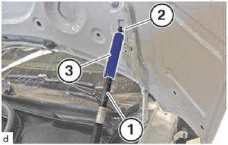
Remove the special tool 0 493 647 (51 2 170)(3) from the ball pin (2).
- SST
- 09800-WA030
Pull off the special tool 0 493 647 (51 2 170) (3) from the gas pressure spring (1).
- SST
- 09800-WA030
Continue to support the hood sub-assembly and repeat the operation on the other side of vehicle.
- CAUTION:
- ·
Shutting hood sub-assembly or tailgate.
Danger of injury!
-Support hood sub-assembly/tailgate in fully open position with the aid of a suitable device.
Check the clamp (3) is fitted correctly.
Connect ball socket (1) to ball pin (2).
Continue to support the hood sub-assembly and repeat the operation on the other side of vehicle.
47.ADD ENGINE OIL
12180E
48.INSTALL OIL FILLER CAP ASSEMBLY
49. CHARGE AIR CONDITIONING SYSTEM WITH REFRIGERANT
50.CONNECT CABLE TO NEGATIVE BATTERY TERMINAL
51.ADD ENGINE COOLANT (for High Temperature)
52.ADD ENGINE COOLANT (for Low Temperature)
53.INSPECT FOR COOLANT LEAK (for High Temperature)
54.INSPECT FOR COOLANT LEAK (for Low Temperature)
55. CHECK ENGINE OIL LEVEL
56.ADJUST AUTOMATIC TRANSMISSION FLUID LEVEL
51219
57.INSTALL FRONT SUSPENSION MEMBER LOWER PROTECTOR