H150F MANUAL TRANSMISSION / TRANSAXLE MANUAL TRANSMISSION ASSEMBLY INSTALLATION
PROCEDURE

 31204
1.INSTALL CLUTCH RELEASE FORK SUB-ASSEMBLY
2.INSTALL TRANSFER ASSEMBLY
3.INSTALL MANUAL TRANSMISSION WITH TRANSFER (for 1GR-FE)
- NOTICE:
-
Check that the 2 straight pins are attached to the engine side.
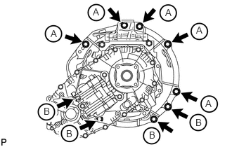
Install the manual transmission with transfer with the 9 bolts.
- Torque:
- for bolt A : 72 N*m (730 kgf*cm, 53 ft.*lbf)
- for bolt B : 37 N*m (380 kgf*cm, 28 ft.*lbf)
- Bolt Length:
Item Length Bolt A 50 mm (1.97 in.) Bolt B 45 mm (1.77 in.)
4.INSTALL MANUAL TRANSMISSION WITH TRANSFER (for 1VD-FTV)
- NOTICE:
-
Check that the 2 straight pins are attached to the engine side.
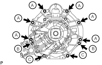
Install the manual transmission with transfer with the 10 bolts.
- Torque:
- for bolt A and B : 72 N*m (730 kgf*cm, 53 ft.*lbf)
- for bolt C : 39 N*m (400 kgf*cm, 29 ft.*lbf)
- Bolt Length:
Item Length Bolt A 45 mm (1.77 in.) Bolt B 50 mm (1.97 in.) Bolt C 70 mm (2.76 in.)
12140
5.INSTALL OIL PAN COVER (for 1VD-FTV)
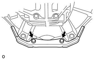
Install the oil pan cover with the 2 bolts.
- Torque:
- 21 N*m (214 kgf*cm, 15 ft.*lbf)
31482
6.INSTALL CLUTCH RELEASE CYLINDER TO FLEXIBLE HOSE TUBE
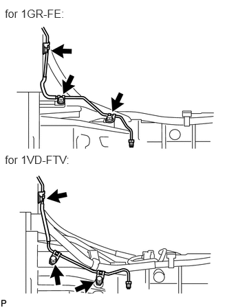
Install the flexible hose tube with the 3 bolts.
- Torque:
- 20 N*m (204 kgf*cm, 15 ft.*lbf)
31470
7.INSTALL CLUTCH RELEASE CYLINDER ASSEMBLY
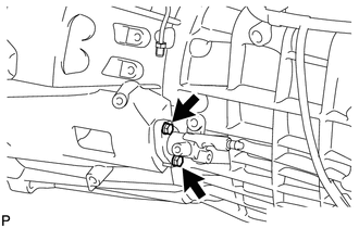
Install the clutch release cylinder with the 2 bolts.
- Torque:
- 12 N*m (120 kgf*cm, 9 ft.*lbf)
31490
8.INSTALL CLUTCH ACCUMULATOR ASSEMBLY
31482D
9.INSTALL CLUTCH RELEASE CYLINDER TO ACCUMULATOR TUBE
31121
10.INSTALL NO. 1 CLUTCH HOUSING COVER
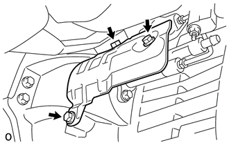
Install the housing cover with the 3 bolts.
- Torque:
- 12 N*m (120 kgf*cm, 9 ft.*lbf)
11.CONNECT WIRE HARNESS (for 1GR-FE)
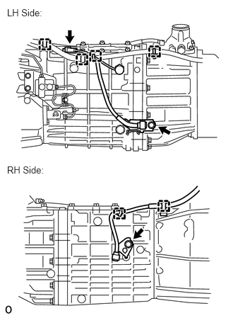
Connect the 6 clamps.
Connect the back-up light switch connector.
Install the 2 bolts.
- Torque:
- for LH side : 29 N*m (296 kgf*cm, 21 ft.*lbf)
- for RH side : 60 N*m (612 kgf*cm, 44 ft.*lbf)
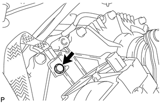
Connect the ground cable with the bolt.
- Torque:
- 8.0 N*m (82 kgf*cm, 71 in.*lbf)
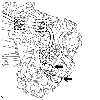
Connect the 2 connectors and 3 clamps.
12.CONNECT WIRE HARNESS (for 1VD-FTV)
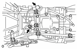
Connect the 5 clamps.
Connect the back-up light switch connector.
Connect the shift position switch connector.
Connect the ground cable with the bolt.
- Torque:
- 8.0 N*m (82 kgf*cm, 71 in.*lbf)
Connect the 2 connectors and 3 clamps.
36407
13.INSTALL TRANSFER BREATHER HOSE SUB-ASSEMBLY (for 1GR-FE)
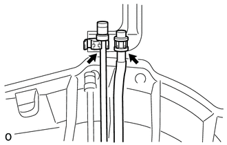
Connect the 2 breather hoses to the bracket.
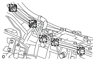
Connect the 5 clamps.
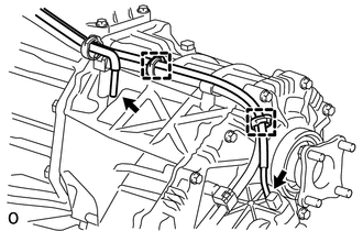
Connect the breather hose to the transfer and actuator, and attach the 2 clamps.
36407
14.INSTALL TRANSFER BREATHER HOSE SUB-ASSEMBLY (for 1VD-FTV)
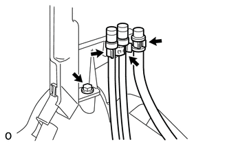
Install the bracket with the bolt.
Connect the 3 breather hoses to the bracket.
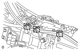
Connect the 3 clamps.
Connect the breather hose to the transfer and actuator, and attach the 2 clamps.
12371
15.INSTALL REAR NO. 1 ENGINE MOUNTING INSULATOR
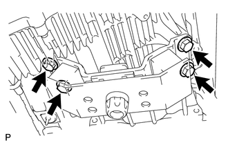
Install the engine mounting insulator to the transmission with the 4 bolts.
- Torque:
- 59 N*m (602 kgf*cm, 44 ft.*lbf)
51203
16.INSTALL NO. 2 FRAME CROSSMEMBER SUB-ASSEMBLY
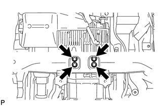
Install the frame crossmember to the rear engine mounting insulator with the 4 bolts.
- Torque:
- 37 N*m (377 kgf*cm, 27 ft.*lbf)
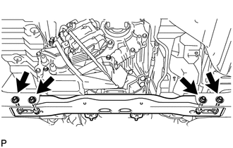
Install the frame crossmember to the vehicle body with the 4 bolts, 4 washers and 4 nuts.
T = 110 N*m{ 1,122 kgf*cm 81 ft.*lbf }
28100
17.INSTALL STARTER ASSEMBLY (for 1GR-FE)
17119
18.INSTALL NO. 2 MANIFOLD STAY (for 1GR-FE)
17118
19.INSTALL MANIFOLD STAY (for 1GR-FE)
17410
20.INSTALL EXHAUST PIPE (for 1GR-FE)
17410
21.INSTALL EXHAUST PIPE (for 1VD-FTV)
37140
22.INSTALL FRONT PROPELLER SHAFT ASSEMBLY
37110
23.INSTALL PROPELLER SHAFT ASSEMBLY
24.ADD MANUAL TRANSMISSION OIL
25.INSPECT TRANSMISSION OIL
36179
26.INSTALL LOWER TRANSFER CASE PROTECTOR
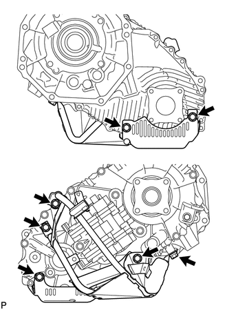
Install the lower transfer case protector with the 7 bolts.
- Torque:
- 14 N*m (139 kgf*cm, 10 ft.*lbf)
33183
27.INSTALL TRANSFER DYNAMIC DAMPER (for 1VD-FTV)
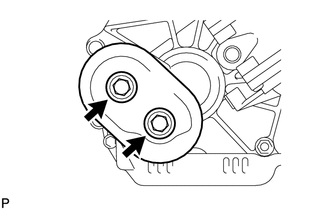
Install the transfer dynamic damper with the 2 bolts.
- Torque:
- 12 N*m (122 kgf*cm, 9 ft.*lbf)
36336
28.INSTALL TRANSFER HEAT INSULATOR
31489
29.INSTALL TUBE CONNECTOR TO FLEXIBLE HOSE TUBE (for 1VD-FTV)
17972
30.INSTALL AIR TUBE SUB-ASSEMBLY LH (for 1VD-FTV)
31418
31.INSTALL CLUTCH HOSE (for 1VD-FTV)
17972
32.INSTALL NO. 2 COOL AIR INLET (w/o Intercooler)
17940D
33.INSTALL INTERCOOLER ASSEMBLY (w/ Intercooler)
12601E
34.INSTALL NO. 1 ENGINE COVER SUB-ASSEMBLY
33530F
35.INSTALL FLOOR SHIFT LEVER ASSEMBLY
Apply MP grease to the tip of the shift lever.
Cover the shift lever cap with a cloth.
Press down on the shift lever cap and rotate it clockwise to install it.
58280A
36.INSTALL SHIFT LEVER BOOT ASSEMBLY
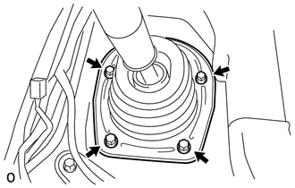
Install the shift lever retainer and shift lever boot with the 4 screws.
58804A
37.INSTALL UPPER CONSOLE PANEL SUB-ASSEMBLY
w/o Console Box Lid (See page Vehicle Interior>INTERIOR PANELS / TRIM>FRONT CONSOLE BOX(w/o Console Box Lid)>INSTALLATION)
w/ Cool Box (See page Vehicle Interior>INTERIOR PANELS / TRIM>FRONT CONSOLE BOX(w/ Cool Box)>INSTALLATION)
w/o Cool Box See page Vehicle Interior>INTERIOR PANELS / TRIM>FRONT CONSOLE BOX(w/o Cool Box)>INSTALLATION)
38.FILL RESERVOIR WITH BRAKE FLUID
39.BLEED CLUTCH LINE
40.CHECK FLUID LEVEL IN RESERVOIR
41.INSPECT FOR CLUTCH FLUID LEAK
42.CONNECT CABLE TO NEGATIVE BATTERY TERMINAL
- NOTICE:
-
When disconnecting the cable, some systems need to be initialized after the cable is reconnected (See page General>INTRODUCTION>REPAIR INSTRUCTION>INITIALIZATION).