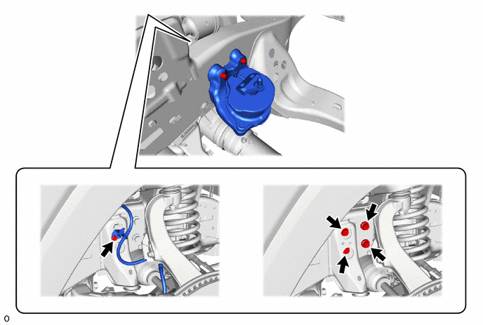
1GR-FE ENGINE MECHANICAL ENGINE ASSEMBLY REMOVAL
CAUTION / NOTICE / HINT
| Procedure | Part Name Code |

|

|

|
|
|---|---|---|---|---|---|
| 1 | PRECAUTION | - | ( ) |
- | - |
| 2 | DISCHARGE FUEL SYSTEM PRESSURE | - | () |
- | - |
| 3 | RELEASE PARKING BRAKE | - | () |
- | - |
| 4 | DISCONNECT CABLE FROM NEGATIVE BATTERY TERMINAL | - | - | - | - |
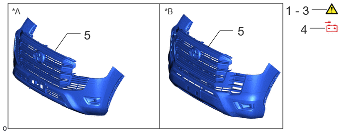
| 5 | FRONT BUMPER ASSEMBLY | - | - | - | - |
| *A | for Standard | *B | for Aero Type |
| Procedure | Part Name Code |
|
|
|
|
|---|---|---|---|---|---|
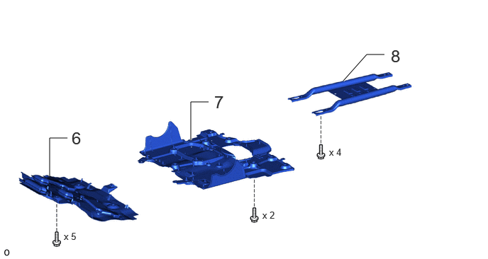
| 6 | NO. 1 ENGINE UNDER COVER ASSEMBLY | 51410 | - | - | - |
| 7 | NO. 2 ENGINE UNDER COVER ASSEMBLY | 51420 | - | - | - |
| 8 | OIL PAN PROTECTOR ASSEMBLY | 51440 | - | - | - |
| Procedure | Part Name Code |
|
|
|
|
|---|---|---|---|---|---|
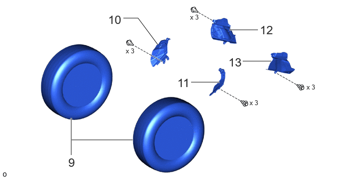
| 9 | FRONT WHEEL | - | - | - | - |
| 10 | FRONT FENDER APRON TRIM PACKING A | 53782 | - | - | - |
| 11 | FRONT FENDER APRON TRIM PACKING B | 53783 | - | - | - |
| 12 | FRONT FENDER APRON TRIM PACKING C | 53784 | - | - | - |
| 13 | FRONT FENDER APRON TRIM PACKING D | 53785B | - | - | - |
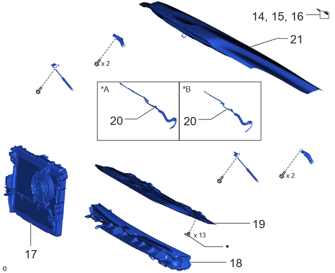
| Procedure | Part Name Code |
|
|
|
|
|---|---|---|---|---|---|
| 14 | DRAIN ENGINE OIL | - | - | () |
- |
| 15 | DRAIN ENGINE COOLANT | - | - | () |
- |
| 16 | DRAIN AUTOMATIC TRANSMISSION FLUID | - | - | () |
- |
| 17 | RADIATOR ASSEMBLY | 16400 | - | - | - |
| 18 | COWL TOP VENTILATOR LOUVER SUB-ASSEMBLY | 55708 | - | - | - |
| 19 | HOOD INSULATOR | 53341B | - | - | - |
| 20 | WINDSHIELD WASHER HOSE ASSEMBLY | 85370 | - | - | - |
| 21 | HOOD SUB-ASSEMBLY | 53301 | - | - | - |
| *A | w/ Heater | *B | w/o Heater |
| ● | Non-reusable part | - | - |
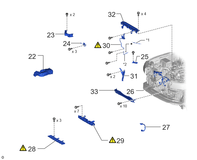
| Procedure | Part Name Code |
|
|
|
|
|---|---|---|---|---|---|
| 22 | INTAKE AIR SURGE TANK | 17129 | - | - | - |
| 23 | HOOD LOCK RELEASE LEVER PROTECTOR | 53525 | - | - | - |
| 24 | HOOD LOCK ASSEMBLY | 53510 | - | - | - |
| 25 | HOOD LOCK CONTROL CABLE COVER | 53629 | - | - | - |
| 26 | ENGINE ROOM MAIN WIRE | 82111 | - | - | - |
| 27 | EXTENSION WIRE ASSEMBLY (w/ Winch) | 82090A | - | - | - |
| 28 | FRONT BUMPER ENERGY ABSORBER (w/o Winch) | 52611 | () |
- | - |
| 29 | FRONT BUMPER CENTER UPPER RETAINER | 52521 | () |
- | - |
| 30 | AIR CONDITIONING TUBE AND ACCESSORY ASSEMBLY AND NO. 2 AIR CONDITIONING TUBE AND ACCESSORY ASSEMBLY | 88710E | () |
- | - |
| 31 | HOOD LOCK SUPPORT BRACE SUB-ASSEMBLY | 53209B | - | - | - |
| 32 | UPPER RADIATOR SUPPORT SUB-ASSEMBLY | 53205 | - | - | - |
| 33 | FRONT CROSS MEMBER | 57161C | - | - | - |
| *1 | HOOD LOCK CONTROL CABLE | *2 | COOLER REFRIGERANT LIQUID PIPE A |
| ● | Non-reusable part | - | - |
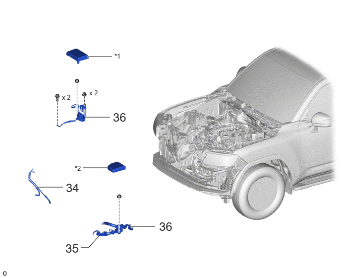
| Procedure | Part Name Code |
|
|
|
|
|---|---|---|---|---|---|
| 34 | OIL COOLER TUBE AND OIL COOLER HOSE | - | - | - | - |
| 35 | ECM CONNECTOR | - | - | - | - |
| 36 | ENGINE WIRE | 82121 | - | - | - |
| *1 | NO. 1 RELAY BLOCK COVER | *2 | NO. 2 RELAY BLOCK COVER |
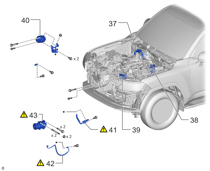
| Procedure | Part Name Code |
|
|
|
|
|---|---|---|---|---|---|
| 37 | WATER HOSE SUB-ASSEMBLY | - | - | - | - |
| 38 | NO. 1 AND NO. 2 FUEL PIPES | 23801P | - | - | - |
| 39 | VANE PUMP ASSEMBLY | 44310 | - | - | - |
| 40 | GENERATOR ASSEMBLY | 27060 | - | - | - |
| 41 | SUCTION HOSE SUB-ASSEMBLY | 88704 | () |
- | - |
| 42 | NO. 1 COOLER REFRIGERANT DISCHARGE HOSE | 88711 | () |
- | - |
| 43 | COMPRESSOR WITH MAGNET CLUTCH | - | () |
- | - |
| ● | Non-reusable part | - | - |
| Procedure | Part Name Code |
|
|
|
|
|---|---|---|---|---|---|
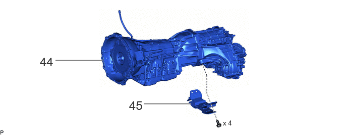
| 44 | AUTOMATIC TRANSMISSION ASSEMBLY | 35000 | - | - | - |
| 45 | REAR ENGINE MOUNTING INSULATOR | 12371A | - | - | - |
| Procedure | Part Name Code |
|
|
|
|
|---|---|---|---|---|---|
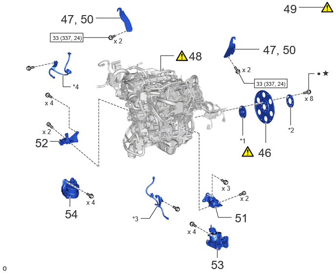
| 46 | DRIVE PLATE AND RING GEAR SUB-ASSEMBLY | 32101 | () |
- | - |
| 47 | INSTALL ENGINE HANGER | - | - | - | - |
| 48 | ENGINE ASSEMBLY | - | () |
- | - |
| 49 | INSTALL ENGINE STAND | - | () |
- | - |
| 50 | REMOVE ENGINE HANGER | - | - | - | - |
| 51 | FRONT NO. 1 ENGINE MOUNTING BRACKET LH | 12315 | - | - | - |
| 52 | FRONT NO. 1 ENGINE MOUNTING BRACKET RH | 12311 | - | - | - |
| 53 | FRONT ENGINE MOUNTING INSULATOR LH | 12362A | - | - | - |
| 54 | FRONT ENGINE MOUNTING INSULATOR RH | 12361E | - | - | - |
| *1 | FRONT DRIVE PLATE SPACER | *2 | REAR DRIVE PLATE SPACER |
| *3 | FRONT NO. 2 FLEXIBLE HOSE BRACKET LH | *4 | FRONT NO. 2 FLEXIBLE HOSE BRACKET RH |

|
N*m (kgf*cm, ft.*lbf): Specified torque | ● | Non-reusable part |
| ★ | Precoated part | - | - |
CAUTION / NOTICE / HINT
The necessary procedures (adjustment, calibration, initialization or registration) that must be performed after parts are removed, installed or replaced during the engine assembly removal/installation are shown below.
| Replaced Part or Performed Procedure | Necessary Procedure | Effect/Inoperative Function when Necessary Procedure not Performed | Link |
|---|---|---|---|
| Battery terminal is disconnected/reconnected | Memorize steering angle neutral point | Parking assist monitor system | () |
| Multi-terrain monitor system | () |
||
| Panoramic view monitor system | () |
||
| Automatic transmission assembly | Reset memory |
·
Large shift shock
·
Engine overruns |
() |
| Automatic transmission fluid | ATF thermal degradation estimate reset | The value of the Data List item "ATF Thermal Degradation Estimate" is not estimated correctly. | |
|
·
Air leaks from intake system
·
Gas leaks from exhaust system |
Inspection after repairs |
·
Poor idle, etc.
·
Engine start function, etc. |
() |
| Engine assembly | Inspection after repairs |
·
Poor idle, etc.
·
Engine start function, etc. |
() |
| Front bumper assembly (Including removal and installation) | Front television camera view adjustment | Panoramic view monitor system | () |
- HINT:
-
When the cable is disconnected/reconnected to the battery terminal, systems temporarily stop operating. However, each system has a function that completes learning the first time the system is used.
-
·
Learning completes when vehicle is driven
Effect/Inoperative Function When Necessary Procedures are not Performed Necessary Procedures Link Lighting system (EXT) Cornering lights Drive the vehicle straight ahead at 35 km/h (22 mph) or more for 5 seconds or more. ( )Pre-collision system Lane tracing assist system Lane departure alert system Adaptive high beam system
·Learning completes when vehicle is operated normally
Effect/Inoperative Function When Necessary Procedures are not Performed Necessary Procedures Link Power back door system Fully close the back door by hand.
- HINT:
-
Initialization is not necessary if the above procedures are performed while the back door is closed.
( )Air conditioning system After the ignition switch is turned to ON, the servo motor and expansion valve standard position is recognized. -
- CAUTION:
-
·
 2.219,0.813 2.646,0.813 false 2.698,0.729 3.01,0.927 0.313,0.198 10 false *a
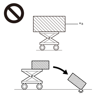
*a An Object Exceeding Weight Limit of Engine Lifter
The engine assembly is very heavy. Be sure to follow the procedure described in the repair manual, or the engine lifter may suddenly drop or the engine assembly may fall off the engine lifter.
·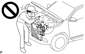
To prevent injury due to contact with an operating fan and generator V-belt or cooling fan, keep your hands and clothing away from the fan and generator V-belt and cooling fans when working in the engine compartment with the engine running.
·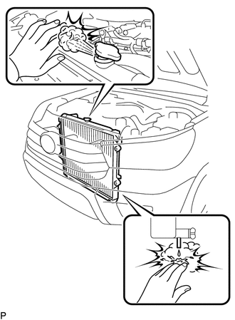
Do not remove the radiator cap sub-assembly, cylinder block drain cock plugs or radiator drain cock plug while the engine and radiator assembly are still hot. Pressurized, hot engine coolant and steam may be released and cause serious burns.
·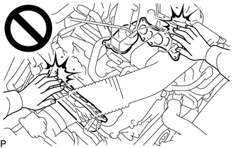
To prevent burns, do not touch the engine, exhaust manifold or other high temperature components while the engine is hot.
·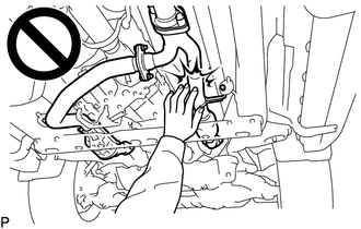
To prevent burns, do not touch the engine, exhaust pipe or other high temperature components while the engine is hot.
PROCEDURE

 1. PRECAUTION
|
|
|
2. DISCHARGE FUEL SYSTEM PRESSURE
3.RELEASE PARKING BRAKE
4.DISCONNECT CABLE FROM NEGATIVE BATTERY TERMINAL
5.REMOVE FRONT BUMPER ASSEMBLY
for Standard:
Click hereVehicle Exterior>EXTERIOR PANELS / TRIM>FRONT BUMPER (for Standard)>REMOVAL
for Aero Type:
Click hereVehicle Exterior>EXTERIOR PANELS / TRIM>FRONT BUMPER (for Aero Type)>REMOVAL
51410 6.REMOVE NO. 1 ENGINE UNDER COVER ASSEMBLY
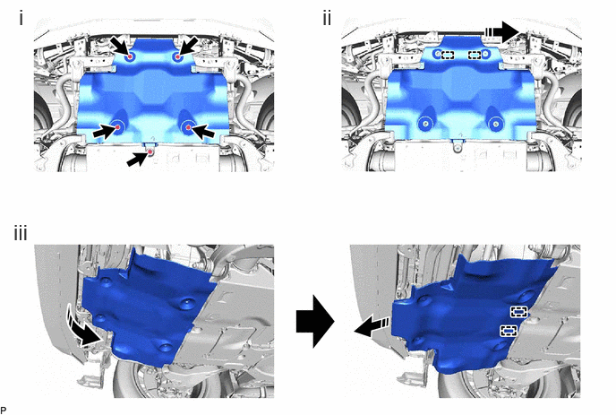

|
Remove in this Direction | - | - |
Remove the 5 bolts.
Move the side of the No. 1 engine under cover assembly facing the front of the vehicle toward the LH side and detach the temporary holding guide.
Remove the No. 1 engine under cover assembly while detaching the 2 temporary holding guides of the No. 1 engine under cover assembly as shown in the illustration.
51420 7.REMOVE NO. 2 ENGINE UNDER COVER ASSEMBLY
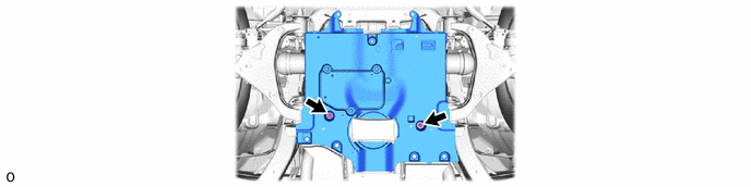
51440 8.REMOVE OIL PAN PROTECTOR ASSEMBLY
9.REMOVE FRONT WHEEL
53782 10.REMOVE FRONT FENDER APRON TRIM PACKING A
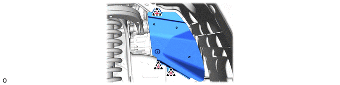
53783 11.REMOVE FRONT FENDER APRON TRIM PACKING B
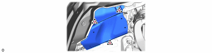
53784 12.REMOVE FRONT FENDER APRON TRIM PACKING C
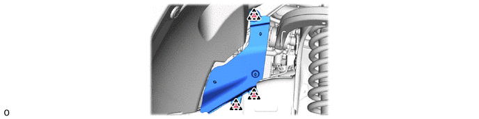
53785B 13.REMOVE FRONT FENDER APRON TRIM PACKING D
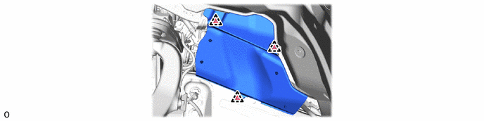
14.DRAIN ENGINE OIL
15.DRAIN ENGINE COOLANT
16.DRAIN AUTOMATIC TRANSMISSION FLUID
16400 17.REMOVE RADIATOR ASSEMBLY
55708 18.REMOVE COWL TOP VENTILATOR LOUVER SUB-ASSEMBLY
53341B 19.REMOVE HOOD INSULATOR
85370 20.REMOVE WINDSHIELD WASHER HOSE ASSEMBLY
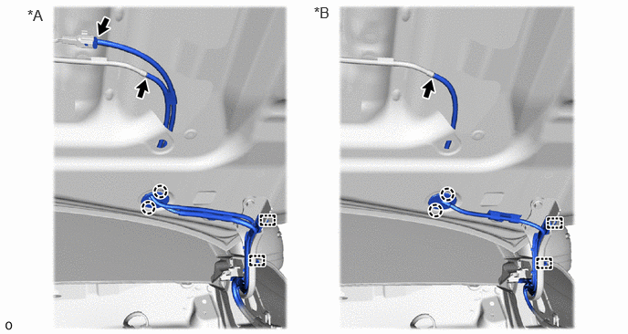
| *A | w/ Heater | *B | w/o Heater |
53301 21.REMOVE HOOD SUB-ASSEMBLY
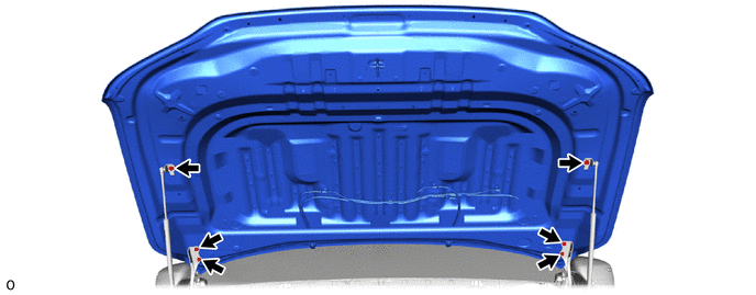
17129 22.REMOVE INTAKE AIR SURGE TANK
53525 23.REMOVE HOOD LOCK RELEASE LEVER PROTECTOR
53510 24.REMOVE HOOD LOCK ASSEMBLY
53629 25.REMOVE HOOD LOCK CONTROL CABLE COVER
82111 26.DISCONNECT ENGINE ROOM MAIN WIRE
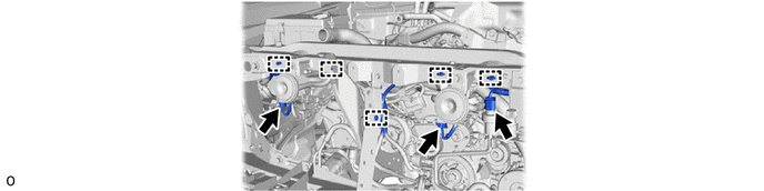
82090A 27.REMOVE EXTENSION WIRE ASSEMBLY (w/ Winch)
52611 28.REMOVE FRONT BUMPER ENERGY ABSORBER (w/o Winch)
|
|
Click here() |
52521 29.REMOVE FRONT BUMPER CENTER UPPER RETAINER
|
|
Click here() |
88710E 30.REMOVE AIR CONDITIONING TUBE AND ACCESSORY ASSEMBLY AND NO. 2 AIR CONDITIONING TUBE AND ACCESSORY ASSEMBLY
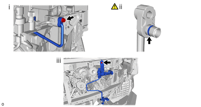
Remove the bolt and cooler refrigerant liquid pipe A.
Remove the O-ring from the cooler refrigerant liquid pipe A.
- NOTICE:
-
Seal the openings of the disconnected parts using vinyl tape to prevent moisture and foreign matter from entering them.
Remove the bolt and air conditioning tube and accessory assembly and No. 2 air conditioning tube and accessory assembly.
53209B 31.REMOVE HOOD LOCK SUPPORT BRACE SUB-ASSEMBLY
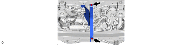
53205 32.REMOVE UPPER RADIATOR SUPPORT SUB-ASSEMBLY
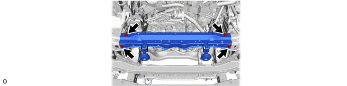
57161C 33.REMOVE FRONT CROSS MEMBER
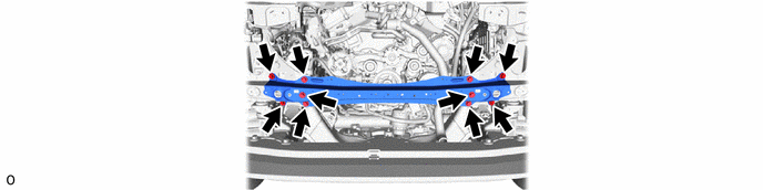
34.REMOVE OIL COOLER TUBE AND OIL COOLER HOSE
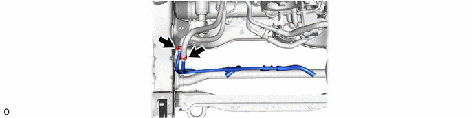
35.DISCONNECT ECM CONNECTOR
82121 36.DISCONNECT ENGINE WIRE
- HINT:
-
After disconnecting the engine wire, secure it with tape or equivalent to keep it out of the way.
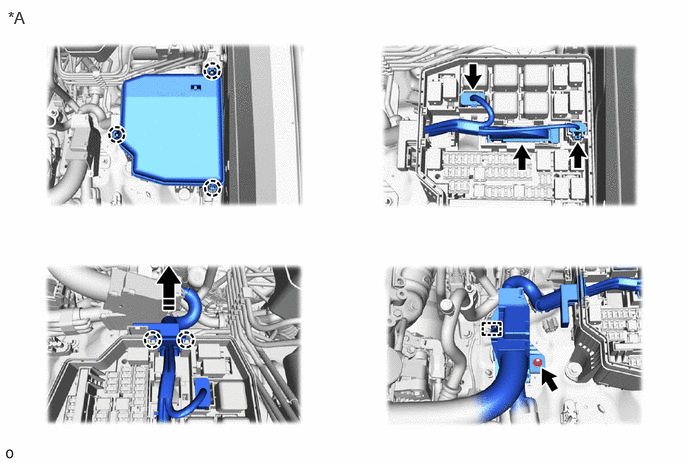
| *A | for LH Side | - | - |
|
|
Remove in this Direction | - | - |
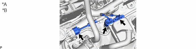
| *A | for LH Side | *B | w/ Secondary Air Injection System |
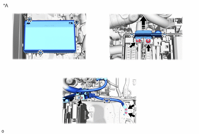
| *A | for RH Side | - | - |
|
|
Remove in this Direction | - | - |
37.DISCONNECT WATER HOSE SUB-ASSEMBLY
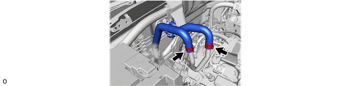
23801P 38.DISCONNECT NO. 1 AND NO. 2 FUEL PIPES
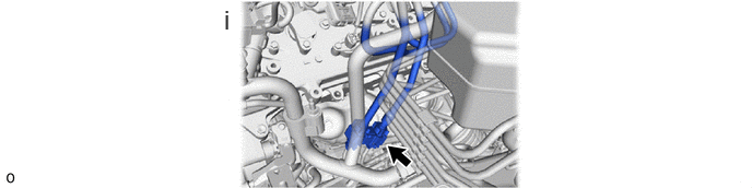
Disconnect the No. 1 and No. 2 fuel pipes.
Click hereEngine / Hybrid System>1GR-FE (FUEL)>FUEL SYSTEM>PRECAUTION
44310 39.DISCONNECT VANE PUMP ASSEMBLY
27060 40.REMOVE GENERATOR ASSEMBLY
88704 41.DISCONNECT SUCTION HOSE SUB-ASSEMBLY
|
|
Click here() |
88711 42.DISCONNECT NO. 1 COOLER REFRIGERANT DISCHARGE HOSE
|
|
Click here() |
43.REMOVE COMPRESSOR WITH MAGNET CLUTCH
|
|
Click here() |
35000 44.REMOVE AUTOMATIC TRANSMISSION ASSEMBLY
12371A 45.REMOVE REAR ENGINE MOUNTING INSULATOR
32101 46.REMOVE DRIVE PLATE AND RING GEAR SUB-ASSEMBLY
|
|
Click here() |
47.INSTALL ENGINE HANGER
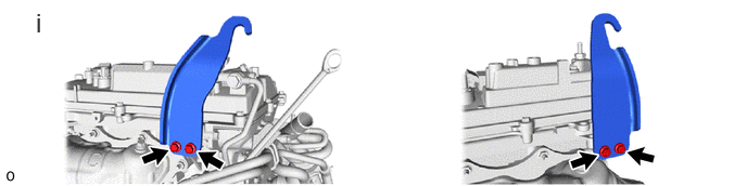
Install the 2 engine hangers with the 4 bolts as shown in the illustration.
- Torque:
- 33 N*m (337 kgf*cm, 24 ft.*lbf)
- HINT:
-
No. 1 Engine Hanger 12281-31110 No. 2 Engine Hanger 12282-31140 Bolt 91671-C0830
48.REMOVE ENGINE ASSEMBLY
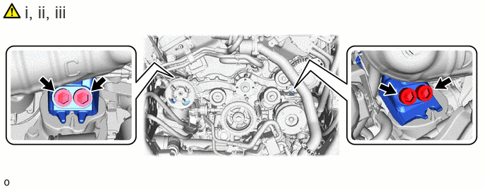
Attach an engine sling device and hang the engine with a chain block.
Using a 17 mm hexagon wrench, remove the 4 hexagon socket head cap bolts.
Remove the engine assembly by operating the engine sling device and chain block.
- NOTICE:
-
·
Make sure that the engine is clear of all wiring and hoses.
·While lowering the engine from the vehicle, do not allow it to contact the vehicle.
49.INSTALL ENGINE STAND

50.REMOVE ENGINE HANGER
12315 51.REMOVE FRONT NO. 1 ENGINE MOUNTING BRACKET LH
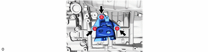
12311 52.REMOVE FRONT NO. 1 ENGINE MOUNTING BRACKET RH
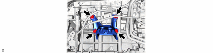
12362A 53.REMOVE FRONT ENGINE MOUNTING INSULATOR LH
- HINT:
-
Perform this procedure only when replacement of the front engine mounting insulator LH is necessary.
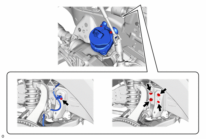
12361E 54.REMOVE FRONT ENGINE MOUNTING INSULATOR RH
- HINT:
-
Perform this procedure only when replacement of the front engine mounting insulator RH is necessary.