1VD-FTV ENGINE MECHANICAL CYLINDER HEAD GASKET(w/o DPF) INSTALLATION
PROCEDURE

 11115 1.SELECT NO. 1 CYLINDER HEAD GASKET
Set the 2 crankshaft pulley set bolts to the crankshaft.
Clean the cylinder block sub-assembly with solvent.
Inspect the protrusions for each cylinder.
Set the piston of the cylinder to be measured to slightly before TDC.
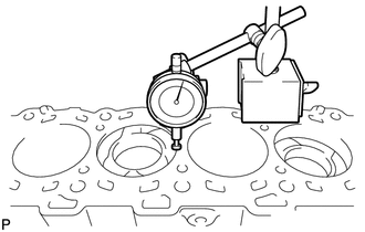
Place a dial indicator on the cylinder block sub-assembly, and set the measuring tip as shown in the illustration.
- NOTICE:
-
Make sure that the dial indicator is at a right angle to the cylinder block sub-assembly top surface.
Set the dial indicator at 0 mm (0 in.).
- HINT:
-
Make sure that the measuring tip is flat against the cylinder block sub-assembly surface and piston head when taking the measurements.
Find where the piston head protrudes most by slowly turning the crankshaft clockwise and counterclockwise.
Measure the piston protrusion value of each cylinder at 2 places as shown in the illustration below, making a total of 8 measurements.
- Standard piston protrusion:
-
0.520 to 0.780 mm (0.0205 to 0.0307 in.)
If the protrusion is not as specified, remove and reinstall the piston and connecting rod.
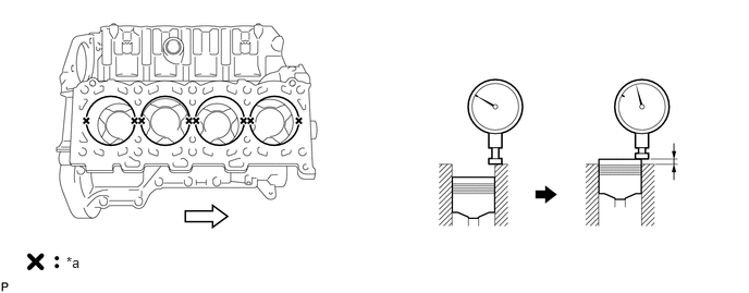
| *a | Measuring Point |

|
Front |
|
|
Front |
Select a new No. 1 cylinder head gasket.
- HINT:
-
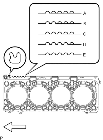
No. 1 cylinder head gaskets are marked A, B, C, D or E accordingly.
- New Installed No. 1 Cylinder Head Gasket Thickness:
-
Item Cutout Specified Condition (*) A 1 1.20 to 1.30 mm (0.0472 to 0.0512 in.) B 2 1.25 to 1.35 mm (0.0492 to 0.0532 in.) C 3 1.30 to 1.40 mm (0.0512 to 0.0551 in.) D 4 1.35 to 1.45 mm (0.0532 to 0.0571 in.) E 5 1.40 to 1.50 mm (0.0551 to 0.0591 in.)
- HINT:
-
*: The specified condition indicates the thickness of the No. 1 cylinder head gasket after tightening the cylinder head sub-assembly RH.
Select the largest piston protrusion value from the measurements and then select a new appropriate No. 1 cylinder head gasket according to the table below.
- Standard Piston Protrusion:
-
Item Specified Condition A 0.520 to 0.575 mm (0.0205 to 0.0226 in.) B 0.575 to 0.625 mm (0.0226 to 0.0246 in.) C 0.625 to 0.675 mm (0.0246 to 0.0266 in.) D 0.675 to 0.725 mm (0.0266 to 0.0285 in.) E 0.725 to 0.780 mm (0.0285 to 0.0307 in.)
Remove the 2 crankshaft pulley set bolts.
11116 2.SELECT NO. 2 CYLINDER HEAD GASKET
Set the 2 crankshaft pulley set bolts to the crankshaft.
Clean the cylinder block sub-assembly with solvent.
Inspect the protrusions for each cylinder.
Set the piston of the cylinder to be measured to slightly before TDC.
Place a dial indicator on the cylinder block sub-assembly, and set the measuring tip as shown in the illustration.
- NOTICE:
-
Make sure that the dial indicator is at a right angle to the cylinder block sub-assembly top surface.
Set the dial indicator at 0 mm (0 in.).
- HINT:
-
Make sure that the measuring tip is flat against the cylinder block sub-assembly surface and piston head when taking the measurements.
Find where the piston head protrudes most by slowly turning the crankshaft clockwise and counterclockwise.
Measure the piston protrusion value of each cylinder at 2 places as shown in the illustration below, making a total of 8 measurements.
- Standard piston protrusion:
-
0.520 to 0.780 mm (0.0205 to 0.0307 in.)
If the protrusion is not as specified, remove and reinstall the piston and connecting rod.
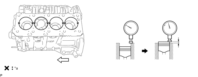
| *a | Measuring Point |
|
Front |
|
|
Front |
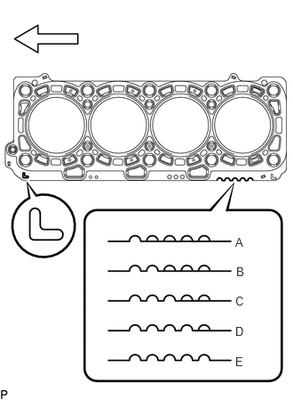
Select a new No. 2 cylinder head gasket.
- HINT:
-
No. 2 cylinder head gaskets are marked A, B, C, D or E accordingly.
- New Installed No. 2 Cylinder Head Gasket Thickness:
-
Item Cutout Specified Condition (*) A 1 1.20 to 1.30 mm (0.0472 to 0.0512 in.) B 2 1.25 to 1.35 mm (0.0492 to 0.0532 in.) C 3 1.30 to 1.40 mm (0.0512 to 0.0551 in.) D 4 1.35 to 1.45 mm (0.0532 to 0.0571 in.) E 5 1.40 to 1.50 mm (0.0551 to 0.0591 in.)
- HINT:
-
*: The specified condition indicates the thickness of the No. 2 cylinder head gasket after tightening the cylinder head sub-assembly LH.
Select the largest piston protrusion value from the measurements and then select a new appropriate No. 2 cylinder head gasket according to the table below.
- Standard Piston Protrusion:
-
Item Specified Condition A 0.520 to 0.575 mm (0.0205 to 0.0226 in.) B 0.575 to 0.625 mm (0.0226 to 0.0246 in.) C 0.625 to 0.675 mm (0.0246 to 0.0266 in.) D 0.675 to 0.725 mm (0.0266 to 0.0285 in.) E 0.725 to 0.780 mm (0.0285 to 0.0307 in.)
Remove the 2 crankshaft pulley set bolts.
11115 3.INSTALL NO. 1 CYLINDER HEAD GASKET
Remove any oil from the contact surface.
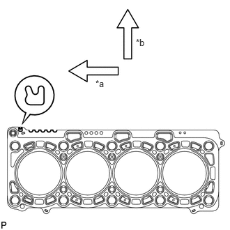
| *a | Front |
| *b | Exhaust Side |
Place the No. 1 cylinder head gasket on the cylinder block sub-assembly surface with the front face of the indicated mark "R" upward and facing the exhaust side.
11116 4.INSTALL NO. 2 CYLINDER HEAD GASKET
Remove any oil from the contact surface.
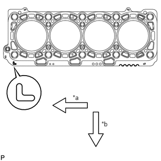
| *a | Front |
| *b | Exhaust Side |
Place the No. 2 cylinder head gasket on the cylinder block sub-assembly surface with the front face of the indicated mark "L" upward and facing the exhaust side.
11101 5.INSTALL CYLINDER HEAD SUB-ASSEMBLY RH
Place the cylinder head sub-assembly RH on the No. 1 cylinder head gasket.
- NOTICE:
-
Ensure that no oil is on the mounting surface of the cylinder head sub-assembly RH.
Apply a light coat of engine oil to the threads and under the heads of the cylinder head set bolts.
Step 1:
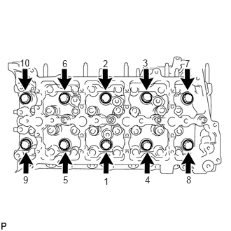
Install and uniformly tighten the 10 cylinder head set bolts with the spacers in several steps, in the sequence shown in the illustration.
- Torque:
- 80 N*m (816 kgf*cm, 59 ft.*lbf)
- HINT:
-
·
The cylinder head set bolts are tightened in 4 progressive steps.
·If a cylinder head set bolt is broken or deformed, replace it.
Step 2:
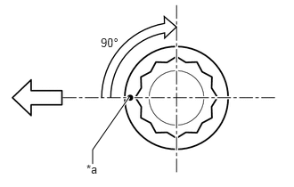
| *a | Painted Mark |
|
|
Front |
Mark the cylinder head set bolt heads with paint as shown in the illustration.
Tighten the cylinder head set bolts another 90° in the sequence shown in step 1.
Step 3:
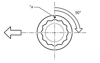
| *a | Painted Mark |
|
|
Front |
Tighten the cylinder head set bolts by an additional 90° in the sequence shown in step 1.
Step 4:
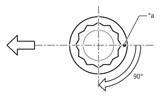
| *a | Painted Mark |
|
|
Front |
Tighten the cylinder head set bolts by an additional 90° in the sequence shown in step 1.
Check that the painted marks are now facing the LH side.
11102 6.INSTALL CYLINDER HEAD SUB-ASSEMBLY LH
Place the cylinder head sub-assembly LH on the No. 2 cylinder head gasket.
- NOTICE:
-
Ensure that no oil is on the mounting surface of the cylinder head sub-assembly LH.
Apply a light coat of engine oil to the threads and under the heads of the cylinder head set bolts.
Step 1:
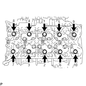
Install and uniformly tighten the 10 cylinder head set bolts with the spacers in several steps, in the sequence shown in the illustration.
- Torque:
- 80 N*m (816 kgf*cm, 59 ft.*lbf)
- HINT:
-
·
The cylinder head set bolts are tightened in 4 progressive steps.
·If a cylinder head set bolt is broken or deformed, replace it.
Step 2:
| *a | Painted Mark |
|
|
Front |
Mark the cylinder head set bolt heads with paint as shown in the illustration.
Tighten the cylinder head set bolts 90° in the sequence shown in step 1.
Step 3:
| *a | Painted Mark |
|
|
Front |
Tighten the cylinder head set bolts another 90° in the sequence shown in step 1.
Step 4:
| *a | Painted Mark |
|
|
Front |
Tighten the cylinder head set bolts by an additional 90° in the sequence shown in step 1.
Check that the painted marks are now facing the LH side.
13750 7.INSTALL NO. 1 VALVE LASH ADJUSTER ASSEMBLY
8.INSTALL NO. 2 VALVE LASH ADJUSTER ASSEMBLY
13801 9.INSTALL NO. 1 VALVE ROCKER ARM SUB-ASSEMBLY
10.INSTALL NO. 2 VALVE ROCKER ARM SUB-ASSEMBLY
11.INSTALL NO. 2 CAMSHAFT BEARING CAP
12.INSTALL NO. 5 CAMSHAFT BEARING CAP
13.SET NO. 1 CYLINDER TO 45° BEFORE TDC
13511 14.INSTALL NO. 1 AND NO. 2 CAMSHAFTS
13053 15.INSTALL NO. 3 AND NO. 4 CAMSHAFTS
11301 16.INSTALL TIMING GEAR CASE SUB-ASSEMBLY
11248 17.INSTALL V-BANK SILENCER
22100 18.INSTALL FUEL SUPPLY PUMP ASSEMBLY
19.INSPECT RADIAL BALL BEARING
13613 20.TEMPORARILY INSTALL INJECTION PUMP DRIVE GEAR
21.SET NO. 1 AND NO. 2 CAMSHAFTS TO TDC/COMPRESSION
13581 22.INSTALL NO. 1 IDLE GEAR SHAFT
13525 23.INSTALL NO. 1 IDLE GEAR
24.TIGHTEN INJECTION PUMP DRIVE GEAR NUT
25.CHECK NO. 1 CYLINDER AT TDC/COMPRESSION
13529G 26.INSTALL NO. 2 CAMSHAFT TIMING SPROCKET AND NO. 2 CHAIN SUB-ASSEMBLY
13523 27.INSTALL NO. 1 CAMSHAFT TIMING SPROCKET AND NO. 1 CHAIN SUB-ASSEMBLY
13522 28.INSTALL PUMP DRIVE SHAFT GEAR
29.INSTALL NO. 2 CHAIN VIBRATION DAMPER
30.INSTALL NO. 2 CHAIN TENSIONER SLIPPER
31.INSTALL NO. 2 CHAIN TENSIONER ASSEMBLY
13561 32.INSTALL NO. 1 CHAIN VIBRATION DAMPER
13559 33.INSTALL NO. 1 CHAIN TENSIONER SLIPPER
13540 34.INSTALL NO. 1 CHAIN TENSIONER ASSEMBLY
19315 35.INSTALL NO. 1 CRANKSHAFT POSITION SENSOR PLATE
36.CHECK NO. 1 CYLINDER AT TDC/COMPRESSION
11302A 37.INSTALL FRONT CRANKSHAFT OIL SEAL
11302 38.INSTALL TIMING CHAIN COVER SUB-ASSEMBLY
17111 39.TEMPORARILY INSTALL INTAKE MANIFOLD
17112 40.TEMPORARILY INSTALL NO. 2 INTAKE MANIFOLD
17114D 41.TEMPORARILY INSTALL NO. 3 INTAKE MANIFOLD
23670 42.INSTALL INJECTOR ASSEMBLY (for Bank 1)
23670 43.INSTALL INJECTOR ASSEMBLY (for Bank 2)
17114D 44.REMOVE NO. 3 INTAKE MANIFOLD
17112 45.REMOVE NO. 2 INTAKE MANIFOLD
17111 46.REMOVE INTAKE MANIFOLD
11213 47.INSTALL CYLINDER HEAD COVER GASKET
11202 48.INSTALL CYLINDER HEAD COVER SUB-ASSEMBLY LH
11201 49.INSTALL CYLINDER HEAD COVER SUB-ASSEMBLY
23681D 50.INSTALL NOZZLE HOLDER SEAL RH
23681E 51.INSTALL NOZZLE HOLDER SEAL LH
12270 52.INSTALL OIL SEPARATOR ASSEMBLY
12101 53.CHECK OIL PAN SUB-ASSEMBLY
12101 54.INSTALL OIL PAN SUB-ASSEMBLY
15620 55.INSTALL OIL FILTER CAP ASSEMBLY WITH ELEMENT
15614 56.INSTALL LOWER OIL FILTER ELEMENT COVER
12102A 57.CHECK NO. 2 OIL PAN SUB-ASSEMBLY
12102A 58.INSTALL NO. 2 OIL PAN SUB-ASSEMBLY
12140 59.INSTALL OIL PAN COVER
11452 60.INSTALL ENGINE OIL LEVEL DIPSTICK GUIDE
12142 61.INSTALL NO. 2 ENGINE OIL LEVEL DIPSTICK GUIDE
15301 62.INSTALL ENGINE OIL LEVEL DIPSTICK
63.CONNECT VACUUM HOSE
17293 64.INSTALL TURBOCHARGER STAY
12201 65.INSTALL VENTILATION TUBE SUB-ASSEMBLY
12263 66.CONNECT NO. 3 VENTILATION HOSE
25708 67.CONNECT NO. 3 VACUUM TRANSMITTING PIPE SUB-ASSEMBLY
15474A 68.INSTALL TURBO OIL OUTLET HOSE
69.INSTALL ENGINE WIRE BRACKET
83520 70.INSTALL OIL PRESSURE SENDER GAUGE ASSEMBLY (w/ Oil Pressure Gauge)
83530 71.INSTALL ENGINE OIL PRESSURE SWITCH ASSEMBLY (w/o Oil Pressure Gauge)
15407 72.CONNECT TURBO OIL INLET PIPE SUB-ASSEMBLY
15769 73.CONNECT OIL COOLER PIPE
17878 74.INSTALL NO. 3 INTAKE AIR CONNECTOR PIPE
17141 75.INSTALL EXHAUST MANIFOLD RH
17142 76.INSTALL EXHAUST MANIFOLD LH WITH TURBOCHARGER SUB-ASSEMBLY
16027 77.INSTALL NO. 1 TURBO WATER PIPE SUB-ASSEMBLY
17361J 78.INSTALL NO. 1 AIR TUBE
17106 79.INSTALL EXHAUST CROSSOVER PIPE SUB-ASSEMBLY
17168 80.INSTALL NO. 2 EXHAUST MANIFOLD HEAT INSULATOR
17167 81.INSTALL NO. 1 EXHAUST MANIFOLD HEAT INSULATOR
13471 82.INSTALL CRANKSHAFT PULLEY
16630H 83.INSTALL IDLER PULLEY ASSEMBLY (w/o Air Conditioning System)
88320 84.INSTALL COOLER COMPRESSOR ASSEMBLY (w/ Air Conditioning System)
44310 85.CONNECT VANE PUMP ASSEMBLY
29300 86.INSTALL VACUUM PUMP ASSEMBLY
44774 87.CONNECT UNION TO CONNECTOR TUBE HOSE
16100 88.INSTALL ENGINE WATER PUMP ASSEMBLY
15778 89.CONNECT NO. 2 OIL COOLER HOSE
15777 90.CONNECT OIL COOLER HOSE
11301K 91.INSTALL CRANKSHAFT POSITION SENSOR
11301M 92.INSTALL CAMSHAFT POSITION SENSOR
12502 93.INSTALL CHAIN COVER AND COMPRESSOR BRACKET SUB-ASSEMBLY
16262 94.CONNECT WATER INLET HOSE
16331A 95.INSTALL THERMOSTAT
16321 96.INSTALL WATER INLET
16620D 97.INSTALL V-RIBBED BELT TENSIONER ASSEMBLY
16603B 98.INSTALL IDLER PULLEY SUB-ASSEMBLY
16307A 99.INSTALL FAN BRACKET SUB-ASSEMBLY
100.INSTALL WATER OUTLET PIPE
16331 101.INSTALL WATER OUTLET
102.INSTALL NO. 3 ENGINE HANGER
17945 103.INSTALL INTERCOOLER SUPPORT BRACKET
17946 104.INSTALL NO. 2 INTERCOOLER SUPPORT BRACKET
28100 105.INSTALL STARTER ASSEMBLY
17111 106.INSTALL INTAKE MANIFOLD
17112 107.INSTALL NO. 2 INTAKE MANIFOLD
16268 108.INSTALL NO. 1 WATER BY-PASS PIPE
23920A 109.INSTALL FUEL COOLER ASSEMBLY
23763 110.INSTALL NO. 3 NOZZLE LEAKAGE PIPE
23764A 111.INSTALL NO. 4 NOZZLE LEAKAGE PIPE
16283 112.INSTALL NO. 6 WATER BY-PASS HOSE
25620 113.INSTALL EGR VALVE ASSEMBLY WITH EGR COOLER ASSEMBLY
25602 114.INSTALL NO. 2 EGR PIPE SUB-ASSEMBLY
25601 115.INSTALL NO. 1 EGR PIPE SUB-ASSEMBLY
16289 116.CONNECT NO. 5 WATER BY-PASS PIPE
17114D 117.INSTALL NO. 3 INTAKE MANIFOLD
17113 118.INSTALL INTAKE PIPE
25614 119.INSTALL NO. 4 EGR PIPE
23801L 120.INSTALL FUEL FILTER TO INJECTION PUMP FUEL PIPE SUB-ASSEMBLY
23810A 121.INSTALL COMMON RAIL ASSEMBLY RH
23820A 122.INSTALL COMMON RAIL ASSEMBLY LH
23705 123.INSTALL NO. 5 INJECTION PIPE SUB-ASSEMBLY
23805B 124.INSTALL NO. 5 FUEL PIPE SUB-ASSEMBLY
23239D 125.INSTALL NO. 1 FUEL HOSE
23706 126.INSTALL NO. 6 INJECTION PIPE SUB-ASSEMBLY
23702 127.INSTALL INJECTION PIPE SUB-ASSEMBLY LH
23701 128.INSTALL INJECTION PIPE SUB-ASSEMBLY RH
17947B 129.INSTALL NO. 3 INTERCOOLER SUPPORT BRACKET
23265 130.INSTALL NO. 1 GAS FILTER
27020 131.INSTALL GENERATOR ASSEMBLY
27280 132.INSTALL GENERATOR SPLASH GUARD COVER ASSEMBLY
82111 133.CONNECT ENGINE ROOM MAIN WIRE
23243C 134.CONNECT FUEL PUMP MOTOR WIRE
16278 135.INSTALL NO. 2 WATER BY-PASS PIPE
16288 136.INSTALL NO. 4 WATER BY-PASS PIPE
25850 137.INSTALL ELECTRIC VACUUM REGULATING VALVE ASSEMBLY
44761 138.INSTALL VACUUM PUMP TO CONNECTOR TUBE
82112 139.CONNECT NO. 2 ENGINE ROOM WIRE
44769 140.INSTALL VACUUM RESERVOIR CONNECT TUBE
23804D 141.INSTALL NO. 4 FUEL PIPE SUB-ASSEMBLY
23284A 142.INSTALL NO. 5 FUEL HOSE
16264 143.CONNECT NO. 2 AND NO. 3 WATER BY-PASS HOSES
26100G 144.INSTALL DIESEL THROTTLE BODY ASSEMBLY (for Bank 2)
26100G 145.INSTALL DIESEL THROTTLE BODY ASSEMBLY (for Bank 1)
19850 146.INSTALL GLOW PLUG ASSEMBLY
17972 147.INSTALL NO. 2 COOL AIR INLET
17971 148.INSTALL NO. 1 COOL AIR INLET
17343D 149.INSTALL NO. 3 AIR HOSE
17362B 150.INSTALL NO. 2 AIR TUBE
17940D 151.INSTALL INTERCOOLER ASSEMBLY
17341F 152.INSTALL NO. 1 AIR HOSE
87249B 153.CONNECT HEATER WATER OUTLET PIPE B
82111 154.CONNECT ENGINE ROOM MAIN WIRE
23271H 155.CONNECT NO. 1 AND NO. 2 FUEL HOSES
156.CONNECT TUBE SUB-ASSEMBLY (w/ Air Conditioning System)
44778 157.CONNECT CONNECTOR TO CHECK VALVE HOSE
87246A 158.CONNECT HEATER WATER HOSE
87250 159.INSTALL HEATER WATER VALVE ASSEMBLY
16400 160.INSTALL RADIATOR ASSEMBLY
74403A 161.INSTALL BATTERY CARRIER SUB-ASSEMBLY
28800 162.INSTALL BATTERY
163.ADD ENGINE OIL
164.CONNECT CABLE TO NEGATIVE BATTERY TERMINAL
165.ADD ENGINE COOLANT
166.BLEED AIR FROM FUEL SYSTEM
167.INSPECT FOR FUEL LEAK
168.INSPECT FOR OIL LEAK
169.INSPECT FOR COOLANT LEAK
170.WARM UP ENGINE
171.INSPECT ENGINE OIL LEVEL
172.INSPECT FOR EXHAUST GAS LEAK
173.INSPECT ENGINE COOLANT LEVEL
174.INSPECT ENGINE IDLE SPEED
175.INSPECT MAXIMUM ENGINE SPEED
176.CHARGE REFRIGERANT (w/ Air Conditioning System)
177.WARM UP ENGINE (w/ Air Conditioning System)
178.CHECK FOR REFRIGERANT GAS LEAK (w/ Air Conditioning System)
53736 179.INSTALL FRONT FENDER APRON SEAL RH
53737B 180.INSTALL FRONT FENDER APRON SEAL LH