2NR-VE ENGINE MECHANICAL ENGINE ASSEMBLY REMOVAL
CAUTION / NOTICE / HINT
- CAUTION:
-
The engine assembly with transmission is very heavy. Be sure to follow the procedure described in the repair manual, or the engine lifter may suddenly drop.
PROCEDURE

 1. DISCHARGE FUEL SYSTEM PRESSURE
2.PLACE FRONT WHEELS FACING STRAIGHT AHEAD
3.DISCONNECT CABLE FROM NEGATIVE BATTERY TERMINAL
4.REMOVE FRONT WHEELS
51441
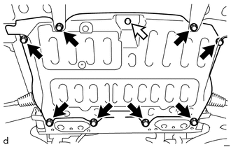
5.REMOVE NO. 1 ENGINE UNDER COVER

|
Bolt |

|
Clip |
Remove the 8 bolts, clip and No. 1 engine under cover.
51443
6.REMOVE NO. 2 ENGINE UNDER COVER (w/ No. 2 Engine Under Cover)
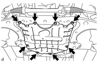
Remove the 8 bolts and No. 2 engine under cover.
7.DRAIN ENGINE COOLANT
8.DRAIN MANUAL TRANSMISSION OIL (for Manual Transmission)
9.DRAIN AUTOMATIC TRANSMISSION FLUID (for Automatic Transmission)
17750A
10.REMOVE AIR CLEANER INLET ASSEMBLY
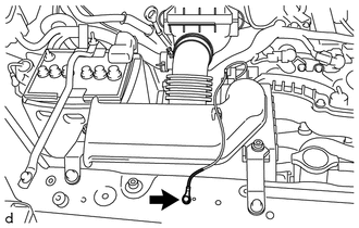
Remove the bolt and disconnect the earth cable.
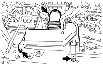
Loosen the hose clamp and remove the 2 bolts and air cleaner inlet assembly.
11.REMOVE BATTERY
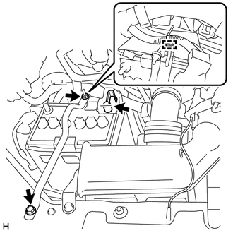
Loosen the nut, and separate the positive (+) battery terminal.
Remove the bolt and loosen the nut.
Disconnect the harness clamp and remove the battery hold down clamp sub-assembly.
Remove the battery cover.
Remove the battery.
74411
12.REMOVE BATTERY CARRIER
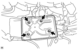
Remove the 4 bolts and battery carrier.
17775A
13.REMOVE NO. 3 AIR CLEANER PIPE BRACKET
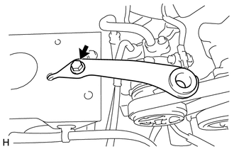
Remove the bolt and No. 3 air cleaner pipe bracket.
16361A
14.REMOVE FAN AND GENERATOR V BELT
16571C
15.REMOVE NO. 1 RADIATOR HOSE
25860
16.REMOVE NO. 1 VACUUM SWITCHING VALVE ASSEMBLY
77754
17.DISCONNECT NO. 1 CHARCOAL CANISTER OUTLET HOSE
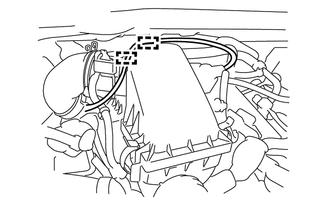
for LHD:
Disengage the 2 guides and disconnect the No. 1 charcoal canister outlet hose from the air cleaner cap sub-assembly.
for RHD:
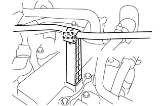
Disengage the clamp and disconnect the No. 1 charcoal canister outlet hose from the charcoal canister outlet guide.
17705
18.REMOVE AIR CLEANER CAP SUB-ASSEMBLY
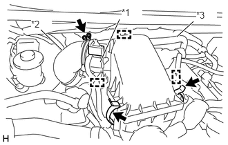
| *1 | Intake Air Flow Meter Assembly |
| *2 | No. 1 Air Cleaner Hose |
| *3 | No. 2 Ventilation Hose |
Disconnect the harness clamp from the air cleaner cap sub-assembly.
Disconnect the harness clamp and connector from the intake air flow meter assembly.
Loosen the hose clamp and disconnect the No. 1 air cleaner hose.
Disengage the guide and disconnect the No. 2 ventilation hose from the air cleaner cap sub-assembly.
Unlock the 2 clamps and remove the air cleaner cap sub-assembly.
17801
19.REMOVE AIR CLEANER FILTER ELEMENT SUB-ASSEMBLY
Remove the air cleaner filter element sub-assembly.
20.REMOVE AIR CLEANER CASE SUB-ASSEMBLY
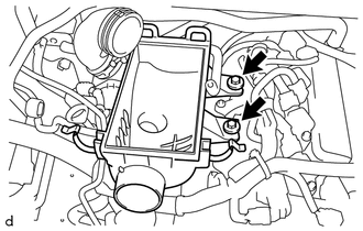
Remove the 2 bolts and air cleaner case sub-assembly.
17881
21.REMOVE NO. 1 AIR CLEANER HOSE
44730A
22.REMOVE NO. 1 VACUUM HOSE (for LHD)
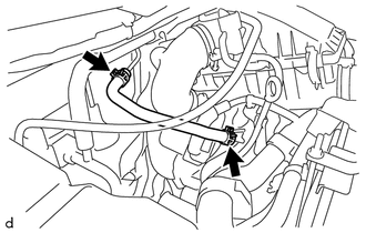
Loosen the 2 clips and remove the No. 1 vacuum hose.
44730A
23.DISCONNECT NO. 1 VACUUM HOSE (for RHD)
88320
24.SEPARATE COOLER COMPRESSOR ASSEMBLY
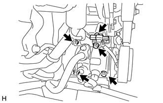
Disconnect the connector.
Remove the 4 bolts and separate the cooler compressor assembly.
- HINT:
-
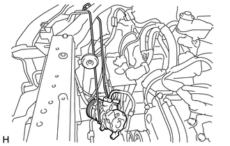
-
It is not necessary to completely remove the cooler compressor assembly. With the hoses connected to the cooler compressor assembly, hang the cooler compressor assembly on the vehicle body with a rope.
82661
25.REMOVE NO. 1 RELAY BLOCK COVER
26.DISCONNECT ENGINE WIRE
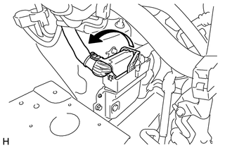
Pull up the lever to disconnect the ECM connector.
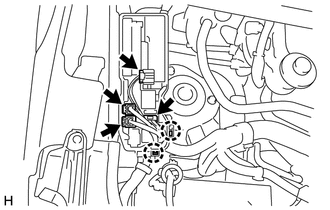
Disconnect the 4 connectors.
Disengage the 2 claws and disconnect the engine wire from the engine room relay block.
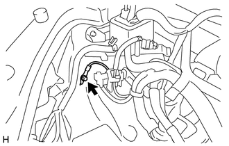
Remove the bolt and disconnect the engine wire from the body.
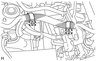
Engage the 2 harness clamps and disconnect the engine wire.
87245X
27.DISCONNECT HEATER WATER HOSE (w/ Heater)
87246X
28.DISCONNECT NO. 2 HEATER WATER HOSE (w/ Heater)
45220
29.SEPARATE STEERING INTERMEDIATE SHAFT ASSEMBLY
37110
30.REMOVE PROPELLER SHAFT ASSEMBLY
33820B
31.SEPARATE TRANSMISSION CONTROL CABLE ASSEMBLY (for Manual Transmission)
33820B
32.SEPARATE TRANSMISSION CONTROL CABLE ASSEMBLY (for Automatic Transmission)
31470
33.SEPARATE CLUTCH RELEASE CYLINDER ASSEMBLY (for Manual Transmission)
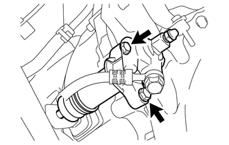
Remove the 2 bolts and separate the clutch release cylinder assembly.
- HINT:
-
It is not necessary to completely remove the clutch release cylinder assembly. With the hoses connected to the clutch release cylinder assembly, hang the clutch release cylinder assembly on the vehicle body with a rope.
89465A
34.REMOVE NO. 2 OXYGEN SENSOR (w/ Air Fuel Ratio Sensor)
17410
35.DISCONNECT FRONT EXHAUST PIPE ASSEMBLY
58151A
36.REMOVE NO. 1 FLOOR HEAT INSULATOR
17410
37.REMOVE FRONT EXHAUST PIPE ASSEMBLY
17451
38.REMOVE EXHAUST PIPE GASKET
23841B
39.REMOVE EFI FUEL PIPE CLAMP
Remove the EFI fuel pipe clamp.
23901
40.DISCONNECT FUEL TUBE SUB-ASSEMBLY
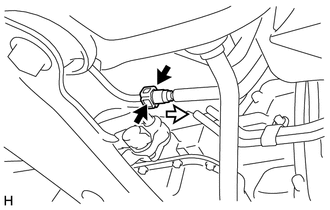
|
|
Pinch |
|
|
Pull |
Pinch the retainer of the fuel tube connector, and then pull the fuel tube connector off of the fuel tank to canister tube sub-assembly.
- NOTICE:
-
Make sure to read the disconnecting the fuel tube connector notice before proceeding with work.
16572D
41.REMOVE NO. 2 RADIATOR HOSE
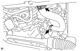
Loosen the 2 hose clamps and remove the No. 2 radiator hose.
32921D
42.REMOVE OIL COOLER INLET HOSE (for Automatic Transmission)
32922A
43.REMOVE OIL COOLER OUTLET HOSE (for Automatic Transmission)
48810
44.SEPARATE FRONT STABILIZER LINK ASSEMBLY LH
48820B
45.INSTALL FRONT STABILIZER LINK ASSEMBLY RH
- HINT:
-
Perform the same procedure as for the LH side.
46.REMOVE FRONT STABILIZER BRACKET
47.DISCONNECT FRONT LOWER SUSPENSION ARM
Use the same procedure for the RH side as for the LH side.
The procedure listed below is for the LH side.
Remove the clip and nut.
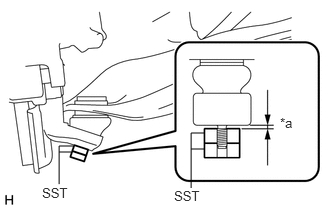
| *a | 1 mm (0.04 in.) |
Install SST to the front lower suspension arm ball joint as shown in the illustration.
- SST
- 09960-20010 (09961-02050)
- NOTICE:
-
Check that the clearance measurement between SST and the steering knuckle is 1 mm (0.04 in.).
Using SST, remove the front lower suspension arm ball joint from the steering knuckle as shown in the illustration.
- SST
- 09960-20010 (09961-02050)
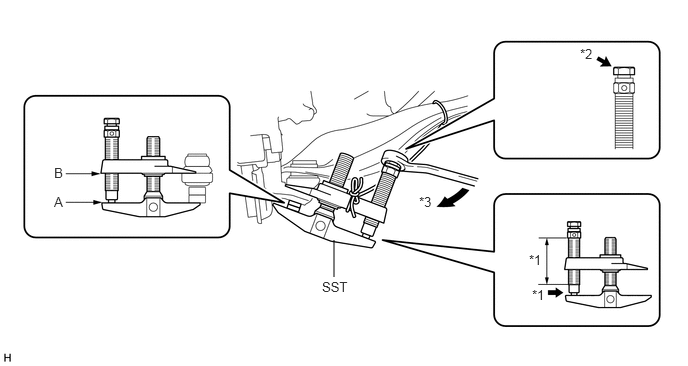
| *1 | Apply grease | *2 | Place the wrench here |
| *3 | Turn | - | - |
- NOTICE:
-
Apply grease to the threads and end of the SST bolt.
- HINT:
- ·
Install SST so that A and B are parallel.
·Be sure to place a wrench on the part indicated in the illustration.
·Do not damage the front lower suspension arm ball joint dust cover.
45047
48.SEPARATE TIE ROD END SUB-ASSEMBLY LH
45046
49.SEPARATE TIE ROD END SUB-ASSEMBLY RH
- HINT:
-
Perform the same procedure as for the LH side.
50.REMOVE ENGINE AND TRANSMISSION ASSEMBLY
for Manual Transmission:
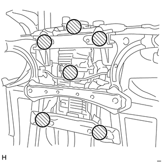

|
Attachment Placement Position |
Place height adjustments or plate lift attachments in the positions shown in the illustration and set an engine lifter underneath the engine assembly with transmission.
- NOTICE:
- ·
Place the height adjustments or plate lift attachments so that the engine assembly with transmission is level.
·Securely support the engine assembly with transmission to prevent it from turning upside down until it is secured to the engine lifter.
·To prevent deformation of the oil pan sub-assembly, never set any attachments against the oil pan sub-assembly of the engine assembly.
·Do not position the height adjustment attachments or plate lift attachments under the front lower suspension crossmember sub-assembly.
for Automatic Transmission:
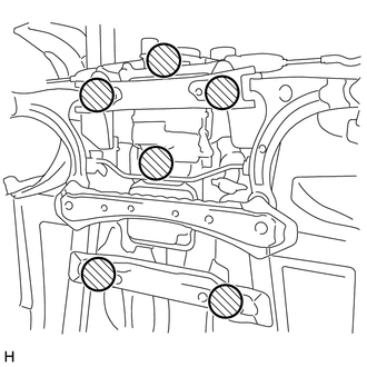
|
|
Attachment Placement Position |
Place height adjustments or plate lift attachments in the positions shown in the illustration and set an engine lifter underneath the engine assembly with transmission.
- NOTICE:
- ·
Place the height adjustments or plate lift attachments so that the engine assembly with transmission is level.
·Securely support the engine assembly with transmission to prevent it from turning upside down until it is secured to the engine lifter.
·To prevent deformation of the oil pan sub-assembly, never set any attachments against the oil pan sub-assembly of the engine assembly.
·To prevent deformation of the transmission oil pan sub-assembly, never set any attachments against the transmission oil pan sub-assembly.
·Do not position the height adjustment attachments or plate lift attachments under the front lower suspension crossmember sub-assembly.
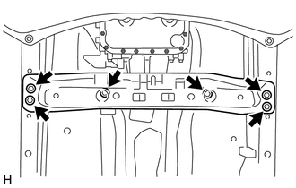
Remove the 6 bolts and the rear engine support member sub-assembly.
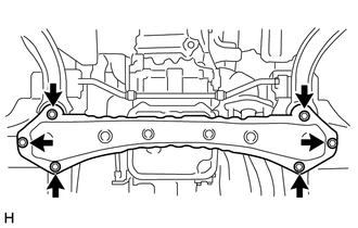
Remove the 6 bolts and the front lower suspension crossmember sub-assembly.
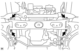
Remove the 4 bolts, operate the engine lifter and slowly remove the engine assembly with transmission from the vehicle.
- NOTICE:
-
When removing the engine assembly with transmission, be careful not to damage any wire harnesses.
Using a rope or belt, secure the engine assembly with transmission to the engine lifter.
- NOTICE:
- ·
Set the engine assembly with transmission so that it is horizontal.
·Do not tighten the rope or belt with a tightening mechanism more than necessary.
51.REMOVE EARTH CABLE
52.REMOVE ENGINE WIRE
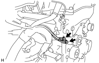
Remove the 2 bolts and disconnect engine wire.
Disconnect all of the clamps and connectors and remove the engine wire from the engine assembly.
17111
53.REMOVE INTAKE MANIFOLD
16591A
54.DISCONNECT RADIATOR PIPE RADIATOR HOSE
87245X
55.REMOVE HEATER WATER HOSE (w/ Heater)
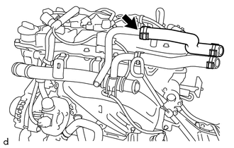
Loosen the clip and remove the heater water hose.
87246X
56.REMOVE NO. 2 HEATER WATER HOSE (w/ Heater)
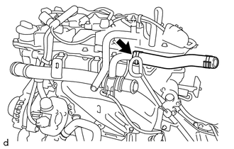
Loosen the clip and remove the No. 2 heater water hose.
16283
57.REMOVE NO. 6 WATER BY-PASS HOSE (w/o Heater)
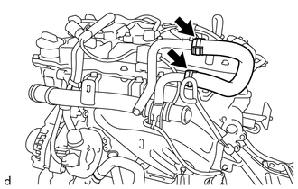
Loosen 2 clips and remove the No. 6 water by-pass hose.
16507
58.REMOVE RADIATOR PIPE SUB-ASSEMBLY
25051
59.REMOVE EXHAUST MANIFOLD CONVERTER SUB-ASSEMBLY
60.INSTALL ENGINE HANGER
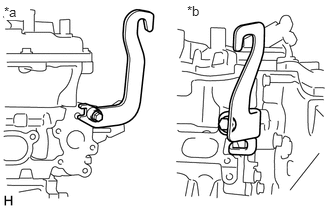
| *a | Intake Side |
| *b | Exhaust Side |
Install the 2 engine hangers with the 2 bolts as shown in the illustration.
- Torque:
- 43 N*m (438 kgf*cm, 32 ft.*lbf)
- HINT:
Part Name Part No. No. 1 Engine Hanger (Black) 12281-0Y070 No. 1 Engine Hanger (Silver) 12281-0Y010 No. 2 Engine Hanger (Black) 12282-BZ140 No. 2 Engine Hanger (Silver) 12282-BZ150 Bolt 90105-T0125
Attach the sling device to the engine hangers and chain block.
- NOTICE:
-
Make sure that the sling angle is correct to prevent the engine assembly with transmission and engine hangers from being damaged or deformed.
28100
61.REMOVE STARTER ASSEMBLY (for Manual Transmission)
28100
62.REMOVE STARTER ASSEMBLY (for Automatic Transmission)
63.REMOVE MANUAL TRANSMISSION ASSEMBLY (for Manual Transmission)
64.REMOVE AUTOMATIC TRANSMISSION ASSEMBLY (for Automatic Transmission)
12361
65.REMOVE FRONT ENGINE MOUNTING INSULATOR
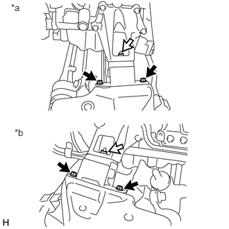
| *a | LH Side |
| *b | RH Side |
|
|
Bolt |
|
|
Nut |
Remove the 4 bolts and 2 nuts, shown in the illustration, then remove the 2 front engine mounting insulators.
51201
66.REMOVE FRONT SUSPENSION CROSSMEMBER SUB-ASSEMBLY
Operate the engine sling device and chain block, then remove the front suspension crossmember sub-assembly.
Using a rope or belt, secure the engine assembly to the engine lifter.
- NOTICE:
- ·
Set the engine assembly so that it is horizontal.
·Do not tighten the rope or belt with a tightening mechanism more than necessary.
12311
67.REMOVE FRONT NO. 1 ENGINE MOUNTING BRACKET RH
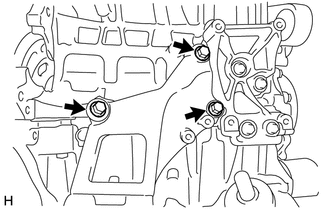
Remove the 3 bolts and front No. 1 engine mounting bracket RH.
12315
68.REMOVE FRONT NO. 1 ENGINE MOUNTING BRACKET LH
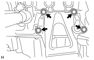
Remove the 4 bolts and front No. 1 engine mounting bracket LH.
31210
69.REMOVE CLUTCH COVER ASSEMBLY (for Manual Transmission)
31250
70.REMOVE CLUTCH DISC ASSEMBLY (for Manual Transmission)
13405
71.REMOVE FLYWHEEL SUB-ASSEMBLY (for Manual Transmission)
32101
72.REMOVE DRIVE PLATE AND RING GEAR SUB-ASSEMBLY (for Automatic Transmission)
73.INSTALL ENGINE STAND
Using a sling device and chain block, install the engine assembly onto the engine stand.
- NOTICE:
- ·
Make sure that the sling angle is correct to prevent the engine assembly and engine hangers from being damaged or deformed.
·Securely support the engine assembly to prevent it from turning upside down until it is secured to an engine stand.