1GD-FTV LUBRICATION OIL PUMP REMOVAL
CAUTION / NOTICE / HINT
- NOTICE:
- ·
When replacing the parts in the following chart (A), replace the No. 1 injection pipe sub-assembly, No. 2 injection pipe sub-assembly and/or fuel inlet pipe sub-assembly with new ones.
Replaced Parts (A) Pipes Requiring New Replacement Injector assembly (including shuffling the injector assemblies between the cylinders) ·No. 1 injection pipe sub-assembly
·No. 2 injection pipe sub-assembly
Supply pump assembly Fuel inlet pipe sub-assembly ·Common rail assembly
·Cylinder block sub-assembly
·Cylinder head sub-assembly
·Cylinder head gasket
·Timing chain case assembly
·No. 1 injection pipe sub-assembly
·No. 2 injection pipe sub-assembly
·Fuel inlet pipe sub-assembly
·After removing the No. 1 injection pipe sub-assembly, No. 2 injection pipe sub-assembly and/or fuel inlet pipe sub-assembly, clean them with a brush and compressed air.
·The injector assembly is a precision instrument. Do not use the injector assembly if it is struck or dropped.
·Make sure foreign matter does not enter the fuel path.
·The supply pump assembly is a precision instrument. Do not use the supply pump assembly if it is struck or dropped.
·Hold the supply pump assembly itself during removal and installation. Do not hold the pre-stroke control valve or fuel pipe, etc.
PROCEDURE

 1.REMOVE ENGINE ASSEMBLY
12633
2.REMOVE NO. 3 ENGINE COVER BRACKET (w/o Urea SCR System)
12632
3.REMOVE NO. 2 ENGINE COVER BRACKET (w/o Urea SCR System)
4.REMOVE ENGINE WIRE
77246C
5.REMOVE FUEL MAIN TUBE SUPPORT
26100G
6.REMOVE DIESEL THROTTLE BODY ASSEMBLY
16278
7.REMOVE NO. 2 WATER BY-PASS PIPE
89481B
8.REMOVE DIFFERENTIAL PRESSURE SENSOR (w/ DPF)
89425
9.REMOVE EXHAUST GAS TEMPERATURE SENSOR (w/ DPF)
25733A
10.REMOVE NO. 1 VACUUM PIPE (w/ DPF)
25734
11.REMOVE NO. 2 VACUUM PIPE (w/ DPF)
17578B
12.REMOVE PIPE CLAMP (w/ DPF)
12631A
13.REMOVE ENGINE COVER BRACKET
23265C
14.REMOVE GAS FILTER
89421C
15.REMOVE DIESEL TURBO PRESSURE SENSOR
25625
16.REMOVE EGR VALVE BRACKET (w/ EGR System)
25612
17.REMOVE NO. 2 EGR PIPE (w/ EGR System)
16206B
18.REMOVE NO. 3 WATER BY-PASS PIPE SUB-ASSEMBLY (w/ EGR Cooler)
16206B
19.REMOVE NO. 3 WATER BY-PASS PIPE SUB-ASSEMBLY (w/o EGR Cooler)
25601
20.REMOVE NO. 1 EGR PIPE SUB-ASSEMBLY
25804
21.REMOVE VACUUM CONTROL VALVE SET (w/ EGR Cooler)
16209
22.REMOVE NO. 4 WATER BY-PASS PIPE SUB-ASSEMBLY
25800
23.REMOVE NO. 1 EGR COOLER AND NO. 2 EGR VALVE ASSEMBLY WITH ELECTRIC EGR CONTROL VALVE ASSEMBLY (w/ EGR System with EGR Cooler)
24.REMOVE EGR VALVE ADAPTER SUB-ASSEMBLY WITH ELECTRIC EGR CONTROL VALVE ASSEMBLY (w/ EGR System without EGR Cooler)
25624
25.REMOVE EGR VALVE ADAPTER SUB-ASSEMBLY (w/o EGR System)
11409
26.REMOVE ENGINE OIL LEVEL DIPSTICK GUIDE
23812D
27.REMOVE NO. 2 FUEL PIPE
28.REMOVE WIRING HARNESS CLAMP BRACKET
17118
29.REMOVE MANIFOLD STAY
22803
30.REMOVE FUEL INJECTION PUMP COVER SUB-ASSEMBLY
23243B
31.REMOVE FUEL PUMP MOTOR WIRE
23273H
32.REMOVE NO. 2 FUEL HOSE
23271H
33.REMOVE NO. 1 FUEL HOSE
23804D
34.REMOVE NO. 4 FUEL PIPE SUB-ASSEMBLY (w/ DPF)
23804D
35.REMOVE NO. 4 FUEL PIPE (w/o DPF)
23815D
36.REMOVE NO. 3 FUEL PIPE
23804C
37.REMOVE FUEL INLET PIPE SUB-ASSEMBLY
23770
38.REMOVE NO. 2 NOZZLE LEAKAGE PIPE ASSEMBLY
17111
39.REMOVE INTAKE MANIFOLD
27148A
40.REMOVE WIRING HARNESS CLAMP BRACKET
23811H
41.REMOVE NO. 1 FUEL PIPE (w/ DPF)
23760
42.REMOVE NOZZLE LEAKAGE PIPE ASSEMBLY
82715
43.REMOVE WIRING HARNESS CLAMP BRACKET
23701
44.REMOVE NO. 1 AND NO. 2 INJECTION PIPE SUB-ASSEMBLY
45.REMOVE HOSE BRACKET
88431
46.REMOVE NO. 1 COMPRESSOR MOUNTING BRACKET
12261
47.REMOVE PCV HOSE (except Cold Area Specification Vehicles)
12229
48.REMOVE PCV PIPE (for Cold Area Specification Vehicles)
49.REMOVE WATER BY-PASS HOSE (w/ Urea SCR System)
16282
50.REMOVE NO. 5 WATER BY-PASS HOSE (w/ DPF)
16281
51.REMOVE NO. 4 WATER BY-PASS HOSE (w/ DPF)
23295D
52.REMOVE NO. 1 INJECTOR HOLDER (w/ DPF)
17168
53.REMOVE NO. 2 EXHAUST MANIFOLD HEAT INSULATOR (w/ DPF)
89467B
54.REMOVE AIR FUEL RATIO SENSOR (w/ DPF)
17167
55.REMOVE NO. 1 EXHAUST MANIFOLD HEAT INSULATOR (w/ DPF)
17167
56.REMOVE NO. 1 EXHAUST MANIFOLD HEAT INSULATOR (w/o DPF)
w/ EGR Cooler:
Click hereEngine / Hybrid System>1GD-FTV (EMISSION CONTROL)>MONOLITHIC CONVERTER (w/o DPF)>REMOVAL
w/o EGR Cooler:
Click hereEngine / Hybrid System>1GD-FTV (ENGINE MECHANICAL)>ENGINE UNIT>REMOVAL
17271
57.REMOVE NO. 1 TURBO INSULATOR (w/ DPF)
17271
58.REMOVE NO. 1 TURBO INSULATOR (w/o DPF)
w/ EGR Cooler:
Click hereEngine / Hybrid System>1GD-FTV (EMISSION CONTROL)>MONOLITHIC CONVERTER (w/o DPF)>REMOVAL
w/o EGR Cooler:
Click hereEngine / Hybrid System>1GD-FTV (ENGINE MECHANICAL)>ENGINE UNIT>REMOVAL
89463C
59.DISCONNECT NO. 1 NITROGEN OXIDES SENSOR (w/ Urea SCR System)
17118
60.REMOVE NO. 2 EXHAUST PIPE SUPPORT STAY (w/ DPF)
61.REMOVE NO. 2 EXHAUST PIPE SUPPORT STAY (w/o DPF)
w/ EGR Cooler:
Click hereEngine / Hybrid System>1GD-FTV (EMISSION CONTROL)>MONOLITHIC CONVERTER (w/o DPF)>REMOVAL
w/o EGR Cooler:
Click hereEngine / Hybrid System>1GD-FTV (ENGINE MECHANICAL)>ENGINE UNIT>REMOVAL
17118
62.REMOVE EXHAUST PIPE SUPPORT STAY (w/ DPF)
63.REMOVE EXHAUST PIPE SUPPORT STAY (w/o DPF)
w/ EGR Cooler:
Click hereEngine / Hybrid System>1GD-FTV (EMISSION CONTROL)>MONOLITHIC CONVERTER (w/o DPF)>REMOVAL
w/o EGR Cooler:
Click hereEngine / Hybrid System>1GD-FTV (ENGINE MECHANICAL)>ENGINE UNIT>REMOVAL
25051
64.REMOVE EXHAUST MANIFOLD CONVERTER SUB-ASSEMBLY (w/ EGR Cooler)
17291
65.REMOVE TURBINE OUTLET ELBOW (w/o EGR Cooler)
89463C
66.REMOVE NO. 1 NITROGEN OXIDES SENSOR (w/ Urea SCR System)
16279
67.REMOVE NO. 3 WATER BY-PASS PIPE
16268
68.REMOVE NO. 1 WATER BY-PASS PIPE
16284
69.REMOVE NO. 1 AND NO. 2 TURBO WATER HOSE
87101
70.REMOVE NO. 1 VISCOUS HEATER BRACKET SUB-ASSEMBLY (w/ Viscous Heater)
17293
71.REMOVE TURBOCHARGER STAY
15474
72.REMOVE TURBO OIL OUTLET PIPE
15407
73.REMOVE TURBO OIL INLET PIPE SUB-ASSEMBLY
17201
74.REMOVE TURBOCHARGER SUB-ASSEMBLY
16207
75.REMOVE NO. 2 WATER BY-PASS PIPE SUB-ASSEMBLY
16304
76.REMOVE WATER OUTLET SUB-ASSEMBLY
16321
77.REMOVE WATER INLET
16331A
78.REMOVE THERMOSTAT
16603
79.REMOVE NO. 1 IDLER PULLEY SUB-ASSEMBLY
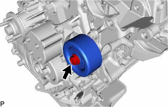
Remove the bolt and No. 1 idler pulley sub-assembly from the generator bracket sub-assembly.
16620
80.REMOVE V-RIBBED BELT TENSIONER ASSEMBLY
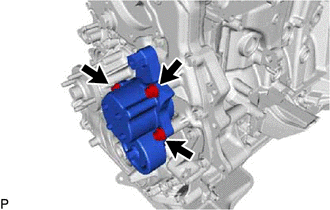
Remove the 3 bolts and V-ribbed belt tensioner assembly from the timing chain cover sub-assembly.
88451B
81.REMOVE VISCOUS HEATER CRANKSHAFT PULLEY (w/ Viscous Heater)
13496
82.REMOVE CRANKSHAFT PULLEY COVER
13471
83.REMOVE CRANKSHAFT PULLEY
16575C
84.REMOVE NO. 1 WATER HOSE CLAMP BRACKET (w/ DPF)
12281A
85.REMOVE NO. 1 ENGINE HANGER
12501
86.REMOVE GENERATOR BRACKET SUB-ASSEMBLY
23670
87.REMOVE INJECTOR ASSEMBLY
23682
88.REMOVE NOZZLE HOLDER GASKET
11401G
89.REMOVE CAMSHAFT POSITION SENSOR
11201
90.REMOVE CYLINDER HEAD COVER SUB-ASSEMBLY
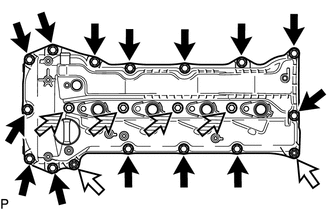

|
Bolt |

|
Nut |

|
Nozzle Holder Clamp Seat |
Remove the 14 bolts, 4 nozzle holder clamp seats, 2 nuts and cylinder head cover sub-assembly from the cylinder head sub-assembly.
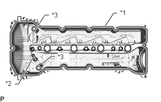
Remove the cylinder head cover gasket, No. 2 cylinder head cover gasket and 2 camshaft bearing cap oil hole gaskets from the cylinder head cover sub-assembly.
| *1 | Cylinder Head Cover Gasket |
| *2 | No. 2 Cylinder Head Cover Gasket |
| *3 | Camshaft Bearing Cap Oil Hole Gasket |
12102A
91.REMOVE NO. 2 OIL PAN SUB-ASSEMBLY
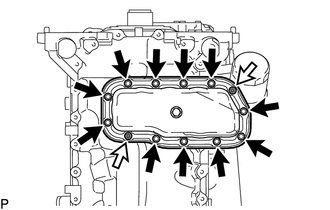
Remove the 2 nuts and 11 bolts.
|
|
Bolt |
|
|
Nut |
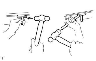
Insert the blade of an oil pan seal cutter between the oil pan sub-assembly and No. 2 oil pan sub-assembly, cut off the applied sealer and remove the No. 2 oil pan sub-assembly.
- NOTICE:
- ·
Be careful not to damage the contact surfaces of the oil pan sub-assembly and No. 2 oil pan sub-assembly.
·Be careful not to damage the oil pan sub-assembly flange.
89491
92.REMOVE ENGINE OIL LEVEL SENSOR
12101
93.REMOVE OIL PAN SUB-ASSEMBLY
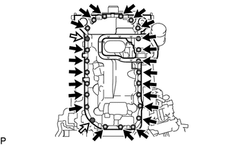
Remove the 2 nuts and 23 bolts.
|
|
Bolt |
|
|
Nut |
Insert the blade of an oil pan seal cutter between the oil pan sub-assembly and cylinder block sub-assembly, cut off the applied sealer and remove the oil pan sub-assembly.
- NOTICE:
- ·
Be careful not to damage the contact surfaces of the oil pan sub-assembly and cylinder block sub-assembly.
·Be careful not to damage the cylinder block sub-assembly flange.
94.SET NO. 1 CYLINDER TO TDC/COMPRESSION
95.REMOVE ENGINE WATER PUMP ASSEMBLY
11324
96.REMOVE TIMING CHAIN COVER PLATE
22100
97.REMOVE SUPPLY PUMP ASSEMBLY
22815A
98.REMOVE INJECTION PUMP INSULATOR
11302
99.REMOVE TIMING CHAIN COVER SUB-ASSEMBLY
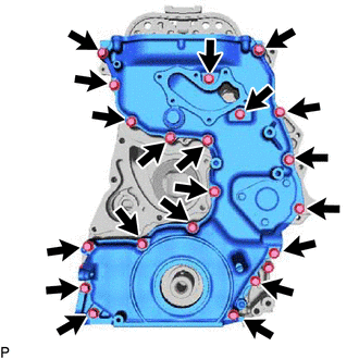
Remove the 20 bolts from the timing chain cover sub-assembly.
Using a screwdriver wrapped in protective tape, remove the timing chain cover sub-assembly by prying the points in the illustration.
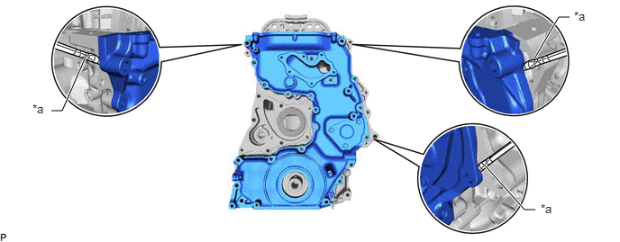
| *a | Protective Tape | - | - |
- NOTICE:
-
Do not damage the contacting surfaces of the timing chain cover sub-assembly and timing chain case assembly.
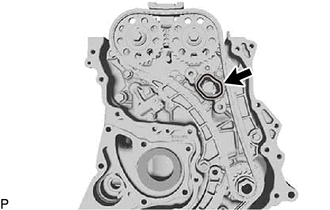
Remove the timing chain case gasket from the timing chain case assembly.
11303A
100.REMOVE FRONT CRANKSHAFT OIL SEAL
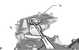
Using a screwdriver and wooden block, pull out the front crankshaft oil seal.
| *a | Protective Tape |
| *b | Wooden Block |
- NOTICE:
-
Do not damage the surface of the front crankshaft oil seal press fit hole.
101.INSPECT BACKLASH OF OIL PUMP GEAR TO OIL PUMP DRIVE GEAR
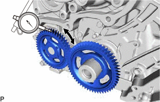
Using a dial indicator, measure the backlash.
- Standard gear backlash:
0.02 to 0.3 mm (0.000787 to 0.0118 in.)
- Maximum gear backlash:
0.42 mm (0.0165 in.)
If the gear backlash is more than the maximum, replace the timing chain case assembly or oil pump drive gear.
13519
102.REMOVE OIL PUMP DRIVE GEAR
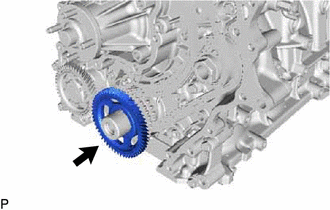
Remove the oil pump drive gear from the crankshaft.
13560A
103.REMOVE NO. 3 CHAIN TENSIONER ASSEMBLY
11991A
104.REMOVE NO.1 BALANCE SHAFT THRUST PLATE
105.REMOVE BALANCE SHAFT TIMING SPROCKET, BALANCE SHAFT GEAR SUB-ASSEMBLY AND NO. 3 CHAIN SUB-ASSEMBLY
13566B
106.REMOVE TIMING CHAIN GUIDE
13550
107.REMOVE NO. 2 CHAIN TENSIONER ASSEMBLY
108.REMOVE NO. 2 CHAIN TENSIONER SLIPPER
13562
109.REMOVE NO. 2 CHAIN VIBRATION DAMPER
13507
110.REMOVE NO. 2 CHAIN SUB-ASSEMBLY
13540
111.REMOVE NO. 1 CHAIN TENSIONER ASSEMBLY
13559
112.REMOVE NO. 1 CHAIN TENSIONER SLIPPER
13561
113.REMOVE NO. 1 CHAIN VIBRATION DAMPER
13506
114.REMOVE CRANKSHAFT TIMING SPROCKET, INJECTION PUMP DRIVE GEAR WITH NO. 1 CHAIN SUB-ASSEMBLY
13523
115.REMOVE CAMSHAFT TIMING SPROCKET
15350
116.REMOVE OIL PRESSURE SWITCHING VALVE ASSEMBLY (w/ 2 Stage Hydraulic Switching Oil Pump System)
15605C
117.REMOVE OIL CHECK VALVE SUB-ASSEMBLY (w/ 2 Stage Hydraulic Switching Oil Pump System)
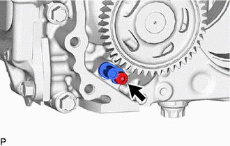
Using a 5 mm hexagon wrench, remove the bolt and oil check valve sub-assembly from the timing chain case assembly.
15605C
118.INSPECT OIL CHECK VALVE SUB-ASSEMBLY (w/ 2 Stage Hydraulic Switching Oil Pump System)
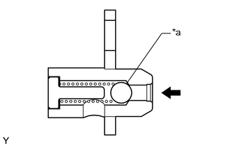
| *a | Ball |
Push the ball of the oil check valve sub-assembly to check if it is stick.
If the ball is stuck, replace the oil check valve sub-assembly.
11310
119.REMOVE TIMING CHAIN CASE ASSEMBLY
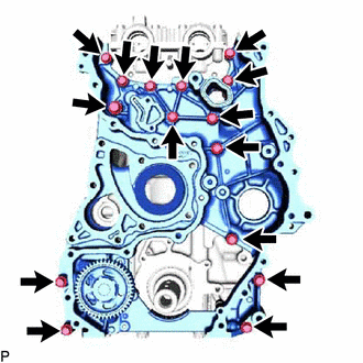
Remove the 15 bolts from the timing chain case assembly.
Using a screwdriver wrapped in protective tape, remove the timing chain case assembly by prying the points in the illustration.
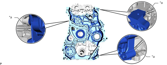
| *a | Protective Tape | - | - |
- NOTICE:
-
Do not damage the contacting surfaces of the timing chain case assembly, cylinder head sub-assembly and cylinder block sub-assembly.
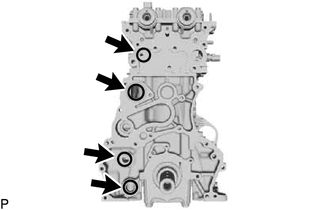
Remove the 4 O-rings from the cylinder head sub-assembly and cylinder block sub-assembly.
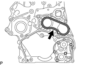
Remove the gasket from the timing chain case assembly.