B48 ENGINE MECHANICAL ENGINE ON-VEHICLE CLEANING
CAUTION / NOTICE / HINT
- CAUTION:
- ·
Hot surfaces.
Risk of burning!
-Perform all work only on components that have cooled down.
- ·
Working on 12 V vehicle electrical system.
Risk of short circuits! Risk of fire!
-Detach battery earth lead from battery.
-For an auxiliary battery: Disconnect battery earth lead of auxiliary battery.
- NOTICE:
- ·
Damage to battery terminal, the safety battery terminal or the intelligent battery sensor (IBS).
Damaged battery terminals can lead to malfunctions or vehicle electrical system faults.
-Pull off battery terminal from battery pole by carefully moving to and fro. Do not pry off using a tool.
PROCEDURE

 1.REMOVE CABLE FROM NEGATIVE BATTERY TERMINAL
Click hereGeneral>MAINTENANCE>B48 BATTERY>REMOVAL
2.REMOVE AND INSTALL BONNET HOOD SUPPORT ASSEMBLY
85010
3.REMOVE FRONT WIPER MOTOR AND LINK ASSEMBLY
53383
4.REMOVE HOOD TO COWL TOP SEAL
53681
5.REMOVE UPPER FRONT SUSPENSION CENTER BRACE
55788A
6.REMOVE COWL TOP VENTILATOR LOUVER PROTECTOR
55789B
7.REMOVE NO. 2 COWL TOP VENTILATOR LOUVER PROTECTOR
12601B
8.REMOVE NO. 1 ENGINE COVER SUB-ASSEMBLY
11271A
9.REMOVE REAR CYLINDER BLOCK COVER
10.REMOVE IGNITION COIL ASSEMBLY
23801P
11.REMOVE NO. 1 FUEL PIPE SUB-ASSEMBLY
23802B
12.REMOVE NO. 2 FUEL PIPE SUB-ASSEMBLY
23100X
13.REMOVE FUEL PUMP ASSEMBLY
23250
14.REMOVE FUEL INJECTOR ASSEMBLY
15370J
15.REMOVE CAM TIMING OIL CONTROL SOLENOID ASSEMBLY
51219
16.REMOVE FRONT LOWER SUSPENSION MEMBER PROTECTOR
17. DRAIN ENGINE COOLANT (for High Temperature)
16020
18.REMOVE WATER PUMP ASSEMBLY
11201
19.REMOVE CYLINDER HEAD COVER SUB-ASSEMBLY
17111
20.REMOVE INTAKE MANIFOLD
21.CLEAN INTAKE PORT
- CAUTION:
- ·
Swirling dirt particles caused by compressed air.
Danger of injury!
-Collect dirt particles, e.g. when blowing out, use cloth to do so.
-Wear safety goggles.
- NOTICE:
- ·
Engine damage due to walnut granules in the combustion chamber.
If walnut granules penetrate the combustion chamber while cleaning the intake ports, engine damage may occur.
-Always clean the intake port with valves of the relevant cylinder closed.
-Set the piston of the relevant cylinder to the top dead center.
-If walnut granules have entered the combustion chamber: Do not turn or start the engine by hand.
-Disassemble the cylinder head and clean all components.
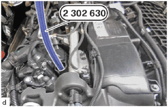
Screw the special tool 2 302 630 into the spark plug thread by hand.
- SST
- 09200-WA660
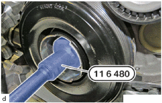
Fit special tool 0 493 380 (11 6 480).
- SST
- 09200-WA190
- NOTICE:
- ·
Damage to the engine.
The engine may be damaged if it is manually rotated in the wrongdirection.
-Always rotate the engine in the correct direction of rotation by hand: a) Clockwise, facing the crankshaft pulley assembly or b) Counter-clockwise, facing the timing chain. (b) only applies when the chain sub-assembly is installed.
Turn the engine by hand using special tool 0 493 380 (11 6 480).
- SST
- 09200-WA190
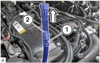
Turn the engine by hand.
When the piston moves up, the journal (2) in the special tool (1) also moves up.
Turn the piston to the top dead center.
In the top dead center, the piston as well as the journal (2) are positioned at the highest point in the special tool (1).
The valves are now closed.
Ensure that the engine is no longer turned further.
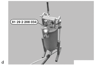
Keep the special tool 2 208 034 , the walnut granules and a standard vacuum cleaner ready.
- SST
- 09200-WA330
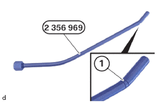
Have the special tool 2 356 969 ready.
- SST
- 09200-WA670
- HINT:
- ·
The front area of the blasting wand is marked with two notches. These may additionally be highlighted in color.
During the blasting process, only pull the blasting wand out of the vacuum adapter until the mark becomes visible.
Observe the mark (1).
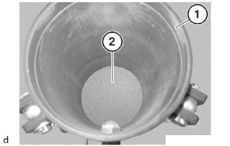
Open blasting device (1).
Fill in walnut granules (2).
- Quantity for each blastingprocess:
2 liters (2.1 US qts, 1.8 Imp. qts)
Close blasting device (1).
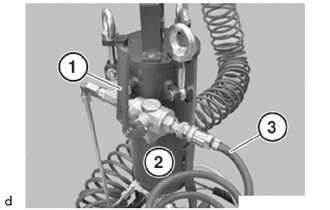
Close the valve (1) on the blasting device (2).
Connect compressed air (3).
- Operating pressure:
600 to 800 kPa (6.1 to 8.2 kgf/cm2, 87 to 116 psi)
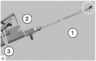
Attach the blasting wand (2) to the blasting device (1).
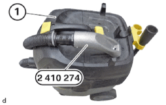
Connect vacuum cleaner (1) with the special tool 2 410 274.
- SST
- 09200-WA340
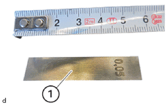
Prepare 2 standard 0.05 mm feeler gauges (1).
Cut 2 feeler gauges (1) to a length of 25 mm.
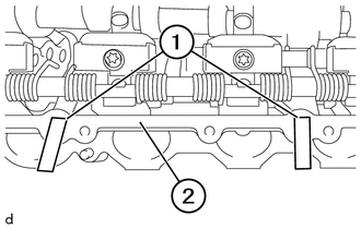
Position the prepared feeler gauges (1) on the blow-by channels of cylinder head sub-assembly (2).
Make sure that the blow-by channels are locked on cylinder head sub-assembly (2) using feeler gauges (1).
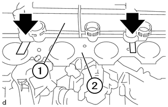
Guide the cylinder head cover sub-assembly (1) in and position it.
Make sure that the feeler gauges (arrows) are positioned correctly between cylinder head cover (1) and the blow-by channels of cylinder head (2).
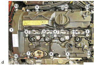
Tighten all E10 bolts in sequence (1) to (15).
- Torque:
- 6.0 N*m (61 kgf*cm, 53 in.*lbf)
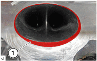
Clean marked areas (1) with a brush.
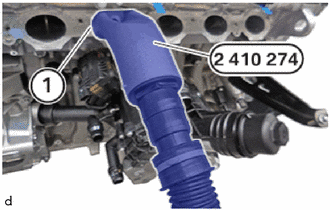
Insert the special tool 2 410 274 in tangential port (1) of the cylinder to be cleaned.
- SST
- 09200-WA340
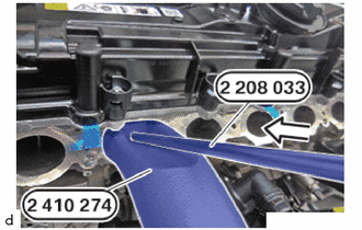
Insert the special tool 2 208 033 in the special tool 2 410 274 in the direction of the arrow.
- SST
- 09200-WA340 09200-WA650
- HINT:
-
Conduct the following operation with the assistance of a second person.
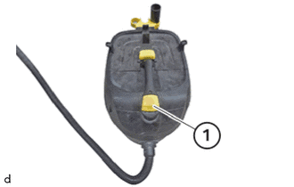
Switch on vacuum cleaner (1).
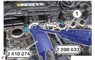
Move and turn the blasting wand in the direction of the arrow.
This removes any dirt in the tangential port.
Open the valve (1).
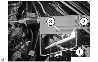
Slide the locking lever (1) forward in the direction of the arrow.
To release the compressed air: Actuate valve (2).
To release the walnut granules and the compressed air: Actuate valves (1) and (2).
Clean the intake port.
- Blast duration with walnut granules:
Approx. 20 s
- Blast duration with purecompressed air for thecomplete blowing out of walnut granules:
Approx. 10 s
Close the valve on the blasting wand.
Check the pressure drop at the pressure measuring device.
Repeat the following steps one after another on all the other cylinders:
Turn the piston of the cylinder to be cleaned to the top dead center.
Clean intake ports.
Loosen all E10 bolts in sequence (15) to (1).
Feed out and remove the cylinder head cover.
Guide out feeler gauges (1) on the blow-by channels of cylinder head (2) and remove them.
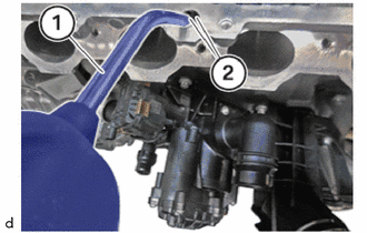
Clean blow-by channels (2) with an air gun (1).
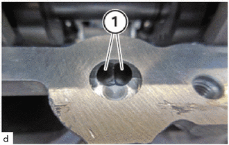
Make sure that there are no walnut granules in the blow-up channels (1).
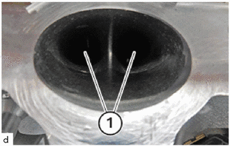
Make sure that there are no walnut granules in the intake ports (1).
17111
22.INSTALL INTAKE MANIFOLD
11201
23.INSTALL CYLINDER HEAD COVER SUB-ASSEMBLY
16020
24.INSTALL WATER PUMP ASSEMBLY
15370J
25.INSTALL CAM TIMING OIL CONTROL SOLENOID ASSEMBLY
23250B
26.REPLACE FUEL INJECTOR SEAL
23250
27.INSTALL FUEL INJECTOR ASSEMBLY
23470
28.ADJUST FUEL PUMP LIFTER ASSEMBLY
23100X
29.INSTALL FUEL PUMP ASSEMBLY
23802B
30.INSTALL NO. 2 FUEL PIPE SUB-ASSEMBLY
23801P
31.INSTALL NO. 1 FUEL PIPE SUB-ASSEMBLY
32.INSTALL IGNITION COIL ASSEMBLY
11271A
33.INSTALL REAR CYLINDER BLOCK COVER
12601B
34.INSTALL NO. 1 ENGINE COVER SUB-ASSEMBLY
55789B
35.INSTALL NO. 2 COWL TOP VENTINATOR LOUVER PROTECTOR
55788A
36.INSTALL COWL TOP VENTILATOR LOUVER PROTECTOR
53681
37.INSTALL UPPER FRONT SUSPENSION CENTER BRACE
53383
38.INSTALL HOOD TO COWL TOP SEAL
85010
39.INSTALL FRONT WIPER MOTOR AND LINK ASSEMBLY
40.REMOVE AND INSTALL HOOD SUPPORT ASSEMBLY
41.ADD ENGINE COOLANT (for Low Temperature)
42.ADD ENGINE COOLANT (for High Temperature)
43.INSPECT ENGINE COOLANT
44. CHECK ENGINE OIL LEVEL
45.INSTALL CABLE FROM NEGATIVE BATTERY TERMINAL