1VD-FTV ENGINE MECHANICAL ENGINE ASSEMBLY INSTALLATION
CAUTION / NOTICE / HINT
- NOTICE:
-
·
When replacing an injector (including interchanging injectors between cylinders) or common rail, replace the corresponding injection pipes with new ones.
·When fuel lines are disconnected, air may enter the fuel lines, leading to engine starting trouble. Therefore, perform forced regeneration and bleed the air from the fuel lines.
PROCEDURE

 12371 1.INSTALL REAR NO. 1 ENGINE MOUNTING INSULATOR
Install the rear No. 1 engine mounting insulator to the manual transmission with transfer with the 4 bolts.
- Torque:
- 59 N*m (602 kgf*cm, 44 ft.*lbf)
12361 2.INSTALL FRONT ENGINE MOUNTING INSULATOR LH
Install the engine mounting stabilizer and front engine mounting insulator LH with a new nut.
- Torque:
- 71.5 N*m (729 kgf*cm, 53 ft.*lbf)
12361 3.INSTALL FRONT ENGINE MOUNTING INSULATOR RH
Install the engine mounting stabilizer and front engine mounting insulator RH with a new nut.
- Torque:
- 71.5 N*m (729 kgf*cm, 53 ft.*lbf)
12281A 4.INSTALL ENGINE HANGER
5.REMOVE ENGINE STAND
Attach an engine sling device and hang the engine assembly with a chain block.
Lift the engine assembly, and remove it from the engine stand.
Place the engine assembly onto a workbench.
13405 6.INSTALL FLYWHEEL SUB-ASSEMBLY
Temporarily install the flywheel sub-assembly with 8 new bolts.
- NOTICE:
-
·
Align the crankshaft knock pin and flywheel sub-assembly knock pin hole.
·Do not strike or damage the flywheel sub-assembly installation bolts. Be sure to handle them carefully.
·Make sure there is no oil on the bolts.
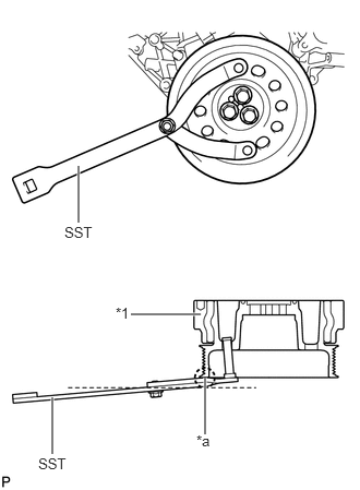
| *1 | Crankshaft Pulley |
| *a | Protective Tape |
Using SST, hold the crankshaft pulley.
- SST
-
09960-10010 (09962-01000, 09963-01000)
- NOTICE:
-
To prevent damage to the crankshaft pulley, apply protective tape to the contact areas of SST and the crankshaft pulley before performing this procedure.
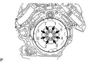
Uniformly install and tighten the 8 bolts in the sequence shown in the illustration.
- Torque:
- 182 N*m (1856 kgf*cm, 134 ft.*lbf)
31250 7.INSTALL CLUTCH DISC ASSEMBLY
31210 8.INSTALL CLUTCH COVER ASSEMBLY
9.INSTALL ENGINE ASSEMBLY
Attach the engine sling device and hang the engine assembly with the chain block.
Slowly lower the engine assembly into the engine compartment.
Install 2 new plate washers and 2 new nuts to the front engine mounting insulator LH and RH.
- Torque:
- 74 N*m (755 kgf*cm, 55 ft.*lbf)
12281A 10.REMOVE ENGINE HANGER
11.INSTALL MANUAL TRANSMISSION WITH TRANSFER
37110 12.INSTALL REAR PROPELLER SHAFT ASSEMBLY
37140 13.INSTALL FRONT PROPELLER SHAFT ASSEMBLY
82112 14.INSTALL NO. 2 ENGINE ROOM WIRE
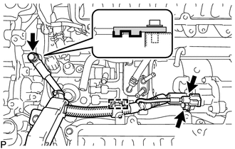
Install the No. 2 engine room wire with the bolt.
- Torque:
- 32 N*m (326 kgf*cm, 24 ft.*lbf)
- HINT:
-
Make sure that the crimped portion of the terminal faces downward as shown in the illustration.
Attach the No. 2 engine room wire clamp.
Connect the starter assembly wire harness with the nut.
- Torque:
- 21 N*m (214 kgf*cm, 15 ft.*lbf)
Connect the starter assembly connector.
17112 15.INSTALL NO. 2 INTAKE MANIFOLD
17111 16.INSTALL NO. 1 INTAKE MANIFOLD
19871 17.INSTALL NO. 1 GLOW PLUG CONNECTOR
18.INSTALL STARTER HOSE BRACKET SUB-ASSEMBLY
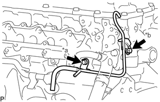
| *a | Bolt A |
| *b | Bolt B |
Install the starter hose bracket sub-assembly with the 2 bolts.
- Torque:
- for Bolt A : 21 N*m (214 kgf*cm, 15 ft.*lbf)
- for Bolt B : 10 N*m (102 kgf*cm, 7 ft.*lbf)
Connect the 2 starter hoses to the starter assembly and starter hose bracket sub-assembly.
16268 19.INSTALL NO. 1 WATER BY-PASS PIPE (w/ DPF)
23841C 20.INSTALL NO. 1 FUEL PIPE CLAMP (w/ DPF)
23881D 21.INSTALL FUEL HOSE BRACKET (w/ DPF)
Install the fuel hose bracket with the bolt.
- Torque:
- 21 N*m (214 kgf*cm, 15 ft.*lbf)
23761A 22.INSTALL NO. 1 NOZZLE LEAKAGE PIPE (w/ DPF)
23901H 23.INSTALL FUEL TUBE SUB-ASSEMBLY (w/ DPF)
23762B 24.INSTALL NO. 2 NOZZLE LEAKAGE PIPE (w/ DPF)
23763 25.INSTALL NO. 3 NOZZLE LEAKAGE PIPE (w/o DPF)
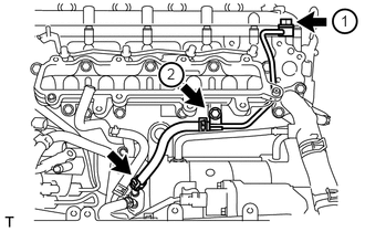
Temporarily install a new gasket and the No. 3 nozzle leakage pipe with the union bolt and bolt.
Tighten the union bolt and bolt in the order shown in the illustration.
- Torque:
- for union bolt : 21 N*m (214 kgf*cm, 15 ft.*lbf)
- for bolt : 10 N*m (102 kgf*cm, 7 ft.*lbf)
Connect the No. 1 fuel hose to the fuel cooler.
23764A 26.INSTALL NO. 4 NOZZLE LEAKAGE PIPE (w/o DPF)
25620 27.INSTALL EGR VALVE ASSEMBLY WITH EGR COOLER ASSEMBLY (w/o DPF)
25680 28.INSTALL EGR COOLER ASSEMBLY WITH NO. 2 EGR VALVE ASSEMBLY (w/ DPF)
25602 29.INSTALL NO. 2 EGR PIPE SUB-ASSEMBLY (w/o DPF)
25601 30.INSTALL NO. 1 EGR PIPE SUB-ASSEMBLY (w/o DPF)
16289 31.CONNECT NO. 5 WATER BY-PASS PIPE (w/o DPF)
17114D 32.INSTALL NO. 3 INTAKE MANIFOLD
17113 33.INSTALL INTAKE PIPE
23763 34.INSTALL NO. 3 NOZZLE LEAKAGE PIPE (w/ DPF)
27148B 35.INSTALL CONNECTING WIRE (w/ DPF)
Attach the 2 clamps to install the connecting wire.
25614 36.INSTALL NO. 4 EGR PIPE (w/o DPF)
25800 37.INSTALL ELECTRIC EGR CONTROL VALVE ASSEMBLY (w/ DPF)
23801L 38.INSTALL FUEL FILTER TO INJECTION PUMP FUEL PIPE SUB-ASSEMBLY
23820A 39.INSTALL COMMON RAIL ASSEMBLY LH
w/ DPF:
Click hereEngine / Hybrid System>1VD-FTV (FUEL)>COMMON RAIL (w/ DPF)>INSTALLATION
w/o DPF:
Click hereEngine / Hybrid System>1VD-FTV (FUEL)>COMMON RAIL (w/o DPF)>INSTALLATION
23765 40.INSTALL NO. 5 NOZZLE LEAKAGE PIPE (w/ DPF)
23810A 41.INSTALL COMMON RAIL ASSEMBLY RH
w/ DPF:
Click hereEngine / Hybrid System>1VD-FTV (FUEL)>COMMON RAIL (w/ DPF)>INSTALLATION
w/o DPF:
Click hereEngine / Hybrid System>1VD-FTV (FUEL)>COMMON RAIL (w/o DPF)>INSTALLATION
23812D 42.INSTALL NO. 2 FUEL PIPE (w/ DPF)
23705 43.INSTALL NO. 5 INJECTION PIPE SUB-ASSEMBLY
23805B 44.INSTALL NO. 5 FUEL PIPE SUB-ASSEMBLY (w/o DPF)
23239D 45.INSTALL NO. 1 FUEL HOSE (w/o DPF)
23706 46.INSTALL NO. 6 INJECTION PIPE SUB-ASSEMBLY
23702 47.INSTALL INJECTION PIPE LH
23764A 48.INSTALL NO. 4 NOZZLE LEAKAGE PIPE (w/ DPF)
Temporarily install a new gasket and No. 4 nozzle leakage pipe with the fuel check valve.
Tighten the fuel check valve.
- Torque:
- 31.5 N*m (321 kgf*cm, 23 ft.*lbf)
Connect the fuel hose.
23701 49.INSTALL INJECTION PIPE RH
16278 50.INSTALL NO. 2 WATER BY-PASS PIPE (w/o DPF)
16288 51.INSTALL NO. 4 WATER BY-PASS PIPE
25850 52.INSTALL ELECTRIC VACUUM REGULATING VALVE ASSEMBLY
23243C 53.CONNECT FUEL PUMP MOTOR WIRE
44761 54.INSTALL VACUUM PUMP TO CONNECTOR TUBE
82112 55.CONNECT NO. 2 ENGINE ROOM WIRE
44769 56.INSTALL VACUUM RESERVOIR CONNECT TUBE
23804D 57.INSTALL NO. 4 FUEL PIPE SUB-ASSEMBLY (w/o DPF)
23284A 58.CONNECT NO. 5 FUEL HOSE (w/o DPF)
16264 59.CONNECT NO. 2 AND NO. 3 WATER BY-PASS HOSES (w/o DPF)
17947B 60.INSTALL NO. 3 INTERCOOLER SUPPORT BRACKET
23265 61.INSTALL NO. 1 GAS FILTER
26100G 62.INSTALL DIESEL THROTTLE BODY ASSEMBLY (for Bank 2)
26100G 63.INSTALL DIESEL THROTTLE BODY ASSEMBLY (for Bank 1)
82111 64.CONNECT ENGINE ROOM MAIN WIRE
w/o DPF:
Connect the engine wire connected to the engine assembly.
Click hereEngine / Hybrid System>1VD-FTV (ENGINE MECHANICAL)>CAMSHAFT (w/o DPF)>INSTALLATION
w/ DPF:
Connect the 2 connectors and 2 wire harness clamps with the 2 bolts.
- Torque:
- 10 N*m (102 kgf*cm, 7 ft.*lbf)
Connect the 2 clamps with the engine wire.
Connect the 2 wire harness brakets with the 2 bolts.
- Torque:
- 10 N*m (102 kgf*cm, 7 ft.*lbf)
Attach the clamp to the No. 3 intercooler support bracket.
Connect the 2 ground wires with the 2 bolts.
Connect the 2 wire harness clamps and attach the engine wire.
Connect the 6 connectors.
Connect the 4 fuel injector connectors.
Connect the engine wire with the 2 bolts.
- Torque:
- 10 N*m (102 kgf*cm, 7 ft.*lbf)
Connect the 2 wire harness clamps and attach the engine wire.
Connect the 6 connectors.
Connect the 4 fuel injector connectors.
Connect the engine wire with the 5 bolts.
- Torque:
- 10 N*m (102 kgf*cm, 7 ft.*lbf)
17972 65.INSTALL NO. 2 COOL AIR INLET
17971 66.INSTALL NO. 1 COOL AIR INLET
17343D 67.INSTALL NO. 3 AIR HOSE
17362B 68.INSTALL NO. 2 AIR TUBE
44774 69.CONNECT UNION TO CONNECTOR TUBE HOSE
82111 70.CONNECT ENGINE ROOM MAIN WIRE
w/o DPF:
Connect the 4 connectors and attach the clamp.
w/ DPF:
Connect the 7 connectors and attach the clamp.
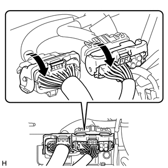
Connect the 2 connectors and lower the levers.
- NOTICE:
-
·
When connecting a connector, make sure that dirt, water and other foreign matter is not stuck between the connector and connector.
·Make sure that the levers are securely lowered.
Attach the 2 engine room main wire clamps.
for LHD:
Attach the engine room main wire clamp.
Connect the ECM connector.
23271H 71.CONNECT NO. 1 AND NO. 2 FUEL HOSES
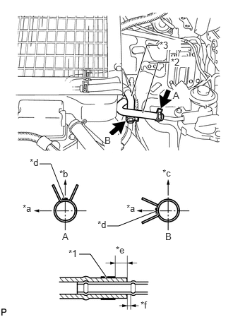
| *1 | Clamp |
| *2 | No. 1 Fuel Hose |
| *3 | No. 2 Fuel Hose |
| *a | Front |
| *b | Upper |
| *c | RH Side |
| *d | White Paint |
| *e | 2.0 to 7.0 mm (0.0787 to 0.276 in.) |
| *f | 0 to 3.0 mm (0 to 0.118 in.) |
w/o DPF:
Connect the No. 1 fuel hose to the fuel filter cap assembly, and slide the clamp to secure the hose.
Connect the No. 1 fuel hose to the fuel filter cap assembly, and slide the clamp to secure the hose.
- HINT:
-
·
Position the claws of the clamps as shown in the illustration.
·Install the clamps so that they are within the fuel hose paint marks.
Connect the No. 2 fuel hose to the fuel pipe, and slide the clamp to secure the hose.
- HINT:
-
·
Position the claws of the clamps as shown in the illustration.
·Install the clamps so that they are within the fuel hose paint marks.
w/ DPF:
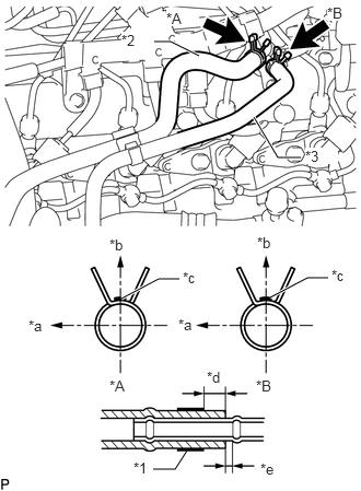
| *1 | Clamp |
| *2 | No. 1 Fuel Hose |
| *3 | No. 2 Fuel Hose |
| *a | Front |
| *b | Upper |
| *c | White Paint |
| *d | 2.0 to 7.0 mm (0.0787 to 0.276 in.) |
| *e | 0 to 3.0 mm (0 to 0.118 in.) |
Connect the No. 1 fuel hose to the fuel filter cap assembly, and slide the clamp to secure the hose.
- HINT:
-
·
Position the claws of the clamps as shown in the illustration.
·Install the clamps so that they are within the fuel hose paint marks.
Connect the No. 2 fuel hose to the fuel pipe, and slide the clamp to secure the hose.
- HINT:
-
·
Position the claws of the clamps as shown in the illustration.
·Install the clamps so that they are within the fuel hose paint marks.
44778 72.CONNECT CONNECTOR TO CHECK VALVE HOSE
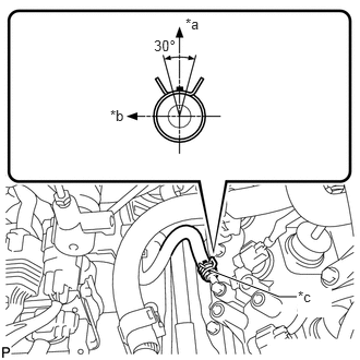
| *a | Upper |
| *b | RH Side |
| *c | White Paint |
w/o DPF:
Connect the connector to check valve hose to the cylinder head cover sub-assembly, and slide the clamp to secure the hose.
- HINT:
-
·
Position the claws of the clamp as shown in the illustration.
·Install the clamp so that it is within the connector to check valve hose paint mark.
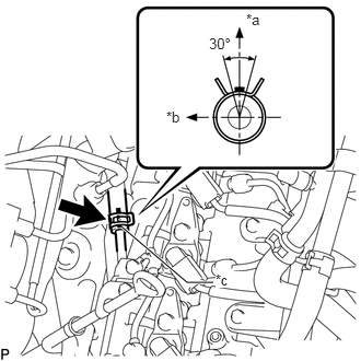
| *a | Upper |
| *b | RH Side |
| *c | White Paint |
w/ DPF:
Connect the connector to check valve hose to the cylinder head cover sub-assembly, and slide the clamp to secure the hose.
- HINT:
-
·
Position the claws of the clamp as shown in the illustration.
·Install the clamp so that it is within the connector to check valve hose paint mark.
88320 73.CONNECT COOLER COMPRESSOR ASSEMBLY (w/ Air Conditioning System)
Install the cooler compressor assembly with the 4 bolts.
- Torque:
- 24 N*m (245 kgf*cm, 18 ft.*lbf)
Connect the cooler compressor assembly connector.
44310 74.CONNECT VANE PUMP ASSEMBLY
Coat a new O-ring with power steering fluid and connect it to the vane pump assembly.
Install the vane pump assembly with the 2 new nuts.
- Torque:
- 29 N*m (296 kgf*cm, 21 ft.*lbf)
Connect the power steering oil pressure switch connector.
74403A 75.INSTALL BATTERY CARRIER SUB-ASSEMBLY
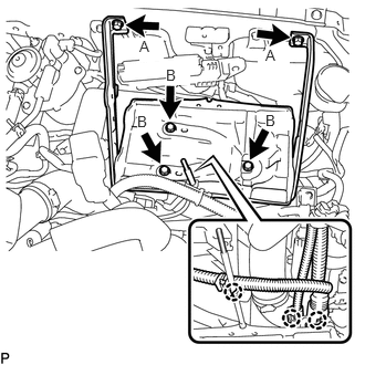
Install the battery carrier sub-assembly with the 5 bolts.
- Torque:
- for bolt A : 12.5 N*m (127 kgf*cm, 9 ft.*lbf)
- for bolt B : 8.0 N*m (82 kgf*cm, 71 in.*lbf)
Attach the 3 wire harness clamps.
Attach the clamp and connect the fusible link block to the battery carrier sub-assembly.
Install the 2 bolts.
- Torque:
- 10 N*m (102 kgf*cm, 7 ft.*lbf)
Attach the wire harness clamp.
Install the bolt and connect the engine wire.
- Torque:
- 8.4 N*m (86 kgf*cm, 74 in.*lbf)
Install the fusible link block cover.
Attach the clamp and connect the No. 2 fuse block to the battery carrier sub-assembly.
Install the bolt.
- Torque:
- 10 N*m (102 kgf*cm, 7 ft.*lbf)
28800 76.INSTALL BATTERY
Install the battery and battery clamp with the bolt and nut.
- Torque:
- for bolt : 8.0 N*m (82 kgf*cm, 71 in.*lbf)
- for nut : 5.0 N*m (51 kgf*cm, 44 in.*lbf)
87240H 77.INSTALL HEATER WATER VALVE ASSEMBLY
87246A 78.CONNECT HEATER WATER HOSE
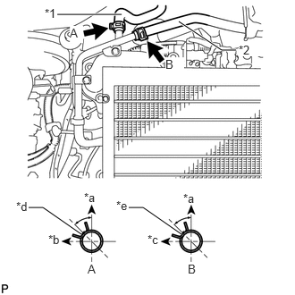
| *1 | Inlet Heater Water Hose |
| *2 | Outlet Heater Water Hose |
| *a | Upper |
| *b | RH Side |
| *c | Front |
| *d | Yellow Paint |
| *e | Blue Paint |
Connect the inlet heater water hose to the outlet heater water pipe B, and slide the clamp to secure the hose.
- HINT:
-
·
Position the claws of the clamps as shown in the illustration.
·Install the clamps so that they are within the heater water hose paint marks.
Connect the outlet heater water hose to the outlet heater water pipe B, and slide the clamp to secure the hose.
- HINT:
-
·
Position the claws of the clamps as shown in the illustration.
·Install the clamps so that they are within the heater water hose paint marks.
17940D 79.INSTALL INTERCOOLER ASSEMBLY
16400 80.INSTALL RADIATOR ASSEMBLY
81.ADD MANUAL TRANSMISSION OIL
82.ADD ENGINE OIL
83.CONNECT CABLE TO POSITIVE BATTERY TERMINAL
84.CONNECT CABLE TO NEGATIVE BATTERY TERMINAL
85. INITIALIZATION AFTER RECONNECTING BATTERY TERMINAL
- HINT:
-
When disconnecting and reconnecting the battery, there is an automatic learning function that completes learning when the respective system is used.
-
Click hereGeneral>SETUP>WHEN DISCONNECTING OR RECONNECTING BATTERY TERMINAL>AUTOMATIC LEARNING CHART
86.ADD ENGINE COOLANT
87.BLEED AIR FROM FUEL SYSTEM
88.CHARGE REFRIGERANT (w/ Air Conditioning System)
89.WARM UP ENGINE (w/ Air Conditioning System)
90.INSPECT FOR REFRIGERANT LEAK (w/ Air Conditioning System)
91.INSPECT FOR FUEL LEAK
92.INSPECT FOR OIL LEAK
93.INSPECT FOR COOLANT LEAK
94.INSPECT FOR EXHAUST GAS LEAK
95.INSPECT ENGINE OIL LEVEL
96.INSPECT IDLE SPEED
97.INSPECT MAXIMUM ENGINE SPEED
53301 98.INSTALL HOOD SUB-ASSEMBLY
Install the hood sub-assembly with the 4 bolts.
- Torque:
- 20 N*m (204 kgf*cm, 15 ft.*lbf)
Connect the washer hose.